Menu

Wednesday, July 26, 2023

NH DEY-3 (ALCo S-1) Part III: Shutter Control and Water Fill

Continuing with the DEY-3 models. Units 0971 and later were delivered with automatic shutter controls, while the earlier units had manual shutter controls. The Proto 2000 model comes with parts for the manual shutter controls. It's a small plastic part that mounts near the fan housing, and a long pipe that goes to the cab. There are starter holes inside the hood to drill out for this part. I didn't have a drill bit long enough so Chris drilled them out for me.


The Precision Scale no. 3321 Hancock vertical check valve looked like a decent match to the small motor mounted on the fan housing with the automatic shutter control. On many roads there's a small rectangular box, which is simply protecting this motor. It would have been easier to model.


To start, I drilled a hole at an angle where I wanted to mount it. I also cut off the small round extension on one end and filed it flat, and filed away the mounting bracket that is around the post. I've been using these tungsten bits a lot and find that the large diameter shaft works well as a handle and often just use them manually like this.


While working on this part, I also drilled and cut out the plastic around the fan so it will be open for the speaker. Once I mounted the part, I soldered one strand from a 32 AWG stranded wire as the conduit.


I drilled the hole for the other end based on a photo.


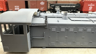
Many earlier units received automatic shutters as well. This motor is on all of them. Some of them received the new radiator shutters, while others retained the original shutters when converted. Not all of the S-1s received the automatic shutter systems, so I'd recommend modeling from photos.

There's also a small water fill pipe missing on the model. I made one by using a piece of 1/64" styrene rod and gluing a piece of 0.035" styrene rod centered on the end.


I cut the larger rod to a thickness that looked good, then glued a second piece of the smaller rod on the other end.


I drilled a hole in the model on the center line roughly halfway between the fan housing and the first panel seam to insert the part.


Then I trimmed off the top and filed it until I liked the dimension.


I also decided I'd rather glue on the fan shutters before painting, so I removed the fan altogether so I wouldn't have to worry about how to mask that. I'll install it after the unit is painted. I also need to figure out what to use for the fan for the other unit, since it started with the round fan housing and I drilled that one out.


Here's how the shutters and shutter actuation systems look on the two units. They've been primed with Badger Stynylrez primer, which I am finding that I love. It's very easy to work with, and appears to be a perfect base coat.

Wednesday, July 19, 2023

NH DEY-3 (ALCo S-1) Part II: Shutters and Whistle

It's been a while since I've been working on the DEY-3 (S-1) locomotives, but Mike Redden brought the new one-piece cabs he's 3D printing at home, instead of the flat kit he has available at Shapeways. In addition he now has the proper fan shutters and the low-profile radiator shutters.

I'm working on two units for HDX-5, nos. 0967 and 0994 for different years.

There are two versions of the Proto 2000 S-1, here's the one with the square fan housing. It comes with an etched fan grate, but unfortunately it should be shutters like an RS-1. Also note the radiator shutters, with 11 wide shutters and how they protrude a couple of inches from the hood. This was a later style of shutters, automatically operated. On the New Haven, this style was on the post-war DEY-3 locomotives, starting with no. 0971.


Chris started a chat with our CAD buddies Chris Zygmunt and Mike Redden last year to produce the correct cooling fan shutters. Mike has them available now, designed to fit the Proto 2000 models. I was able to provide photos and measurements from an RS-1 shutter, which are identical.

I'm not using a walk-over grate. Based on photos, it appears that the New Haven didn't install these until c1954 with the introduction of the "full balloon" paint scheme. Although there are a few photos in other schemes with them, all of the dated ones are 1954 or later.

One photo of 0943 in Hartford has the narrow walk-over grate and it's still in the Pullman Green delivery scheme. Its next documented repaint was April, 1954 in the "full balloon" scheme, and was obviously prior to 1943. But I haven't documented any others, and also not with the narrow grate. 


It's a see-through part with the shutters partially open, which is great because I've mounted the speaker up front. This is mounted on the second version of the Proto model. I drilled out the top and scratch built the square housing to the same dimensions as the other model. Why? Because that version of the model has flush-mounted radiator shutters. Unfortunately, it still has the 11 wide shutters, instead of the 24 narrow shutters on the prototype. Now that Mike has made the correct ones, I'll replace them.


To do that I just drilled a bunch of holes, then cut and filed away the old shutters so I could replace them with the new ones. Mike's part installs from the outside, and the flange covers hides the seam, so it doesn't have to be perfect. Here are a couple of pictures with the new fan and radiator shutters. This will be no. 0967.


Here's a shot of Mike's one-piece cab with the low-profile New Haven roof. I've also shortened the stack to the same height. The bell has been removed (it's mounted under the frame) and the New Haven used a 3-chime whistle instead of a horn.


I'm using a Custom Finishing no. 103 whistle, as it's based on the NH prototypes. It's slightly large/tall, but their shorter whistle is based on a NYC single chime prototype. I'm also using one of the pipes with an elbow from the Precision Scale no. 4839. It's marketed as O-scale parts, but will work well for this. The Precision Scale no. 3321 Hancock vertical check valve (a part that's no longer produced) will be used in the next post...


The pipe has an elbow that is already cored. I shortened the post on the whistle and soldered them together.


Although probably large, I used a strip of 1"x8" styrene because it was wide enough to drill for a Cal Scale no. 512 U-bolt to attach the whistle in the same way the New Haven did.


I scored a second piece of 1"x 8" styrene so I could bend it to make a handle for the other part of the whistle bracket.


You can see how I'm installing it here using styrene cement, and a picture of the prototype behind it. On no. 0967 it's mounted about a foot forward of the cab roof.


On the second unit, no. 0994, it is mounted about three feet forward. you can see the difference in spacing between the two below:


More to come...


Wednesday, July 12, 2023

Designing and Updating Staging

Over time I had added additional staging/storage tracks where I had space. The primary purpose for these is to store locomotives when they are not in use during a session. As I've been preparing the layout for signaling, it occurred to me that it would be useful to minimize the number of turnouts on the signaled track. 

There were seven turnouts to staging/storage tracks along the run-through staging track, but by reconfiguring the arrangement, I can reduce that to two. While these weren't in my original staging design, they were dead space and I decided it would be useful to have storage tracks where locomotives not used during the session could remain on the layout. 

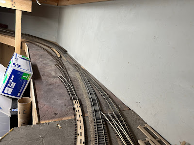
On this side I'll eliminate one turnout on the main, and the second one is moved to a new location. This will create a "lower staging yard" of four short tracks for the RDCs - three long enough for a pair, and the fourth for a single unit. For 1953 sessions, these trains can operate right out of this location. As usual on my layout, they terminate in the same track as they originate.

An additional two tracks will go around behind the Agents desk and will be on a grade. That's fine, because it's storage for locomotives. This replaces the turnout that is currently back there to access these tracks. They will be long enough for the A-B-A and A-B-B-A sets of FA-1/FB-2 locomotives.


I have a general idea of how I think I can fit this using Microengineering Yard Ladder turnouts. I did pick up an extra middle turnout (you can see it in the lower right) but came to the conclusion that it wouldn't fit.

If this were for a scenicked portion of the layout, I would have modified the regular No. 5 or No. 6 Microengineering turnouts so I could curve them to follow the main, but in this case a straight ladder is fine...provided I can get reasonable radius curves to enter and exit.


I have a further two yard ladder turnouts to fit at the far end, so I mock up some ideas there too. I've tried drawing things out like this, and spent some time in the past with some of the CAD programs designed for model railroads but have found that nothing is as good as just working with track, for me. In part because as I see where things lie, I see other options and can tweak the concept instantly.


I had some cork sheets left over from making the cork board at the Agent's desk and they were the correct thickness so I used those as the roadbed and started connecting track. I'm shooting for a minimum of 26" radius here, but 24" will work just fine if I have to do that. 


This process involves ensuring that the tracks not only fit for this section, but that I'll have enough clearance at the far end for the curve to the second part. At this point, it looks pretty good.


Of course, prior to gluing it down I want to test it with the RDCs too in order to make sure they are long enough.


Looking around the corner, I've switched to Woodland Scenics foam roadbed sheets, since that's what Roger had in stock, and also their 2% grade starters to get up to the higher benchwork as it goes around the corner. 


I have a window cut out in the utility room to access behind the Agent's desk. I need to fill in the track where I removed the turnout - easily accessible but hidden while operating from the layout room. Locomotives can be stored here from the clearance point of the turnout, and I took care (using 85' passenger cars) to ensure clearance around the corner of the desk and between the tracks. The main line track will run along the edge of the cork roadbed, and I can move it further out if needed, to ensure the storage tracks won't interfere with operations.


On the other side, I've already moved the main line turnouts. Like the other side, I had HO scale cork roadbed in the original track arrangement. I found it easier to rip that all out and use the foam sheets instead.

To make this side work, I have a couple of Walthers curved turnouts, one curved Peco, and the rest standard Microengineering ones that I had on hand. I've tried a number of configurations and landed on this. It eliminates 4 main line turnouts.


One track will be sized specifically for the Comet and another track for spare cabooses. That will leave two longer tracks for storage of diesel locomotives not in use. The track through the ladder goes to the Walthers turntable used to turn locomotives during the session. I went with the Walthers one because the controller has a button that will turn the bridge 180 degrees, which is really all I need it for. But I will have room to make storage tracks for the steam locomotives when the time comes.

I used insulated joiners to isolate these storage tracks, and may also add switches so I can turn them off during sessions.