I know I said this was going to be a short couple of posts, but as I've been looking closer at photos, I keep noticing some other details I want to try to include. Case in point, when examining this photo of 0502 and 0503 in Plainville c1948 (photo by Cochrane)...
...I noticed something on the walkway that I hadn't seen before.
I don't know what that little thing is just behind the railing stanchion, but there's one at the other end too:
Looking more closely at this photo of 0509 (photographer unknown), it's there as well:
We can see it more clearly. Examining other photos, they appear to only be on the engineer's side. In part because I want to get better at scratchbuilding, I wanted to see if I could make these. It's another example of something that I have no idea what it is, but all I really need to know is that it is there, and what it looks like.
So I started by drilling into the end of 0.020" styrene rod, and inserting a short piece of 0.010" wire (I think, it was scrap).
After cutting the styrene to a length that looked good, I sliced a thin sliver of 0.030" styrene rod to make the cap:
Then it was a simple matter of drilling a hole in the walkway and installing it:
One tip - really good drill bits. I recently ordered some from Amazon for a slightly different reason. One of the challenges I often struggle with is getting a wire-gauge drill bit chucked up so it is straight. The slightest bit of off-axis alignment means the tip is moving quite a bit out of alignment, often causing it to walk, or break. I thought this design would make it much easier, and it did, since it's a much larger portion to chuck. In fact, it's not much smaller than the maximum my Dremel chuck will accept.

So as I thought, that worked great. What I didn't expect was how sharp they were. The first thing I needed to drill was a hole in the metal frame. It was like drilling styrene it was so easy and fast. They are incredible. I've even used them as their own without the dremel or pin vise, as the 'handle' is large enough as it is. They do break easily with any side-to-side force, but I've broken far fewer since they drill so well. I highly recommend them. They do come in many different sizes, all labeled in mm, so you can consult a chart like this to select the sizes you want.
BARCO Steam Lines
I also cut out the front of the pilot to allow installing the BARCO steam lines as seen in the picture of 0502 and 0503 above. To do this, I notch with the corner/edge of a file to define the width, then continue to shape it with a file.
I used Custom Finishing parts. They are cast in a soft pewter and aren't quite as crisp as the brass ones were. These are spun cast in rubber molds, and it's also clear that the molds are old because many of the parts are incomplete. You can see the difference between these two castings:
In the first one, several of the parts are malformed, including one of the BARCO steam lines, which are the only parts I'm using from this casting. So I recommend ordering at least one extra set of parts. I usually do this anyway, since there's a good chance I'll lose or break a part anyway. If you can find the brass version, grab them. I'm happy that they are still available at all, and an occasionally bad casting is not something I worry about.
After bending the casting so I could glue it against the inside of the pilot, I used 0.010" scrap styrene to put across the bottom to complete it. I did a quick paint/preliminary weathering as well.
Hand Brake Chain Guides
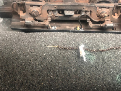
Stephen Wintner asked how I installed the truck chains. I started by drilling the holes for the two parts of the chain guide. The Custom Finishing set has a third part, with the wheel horizontal, but they aren't used on the NH locomotives.
Incidentally, I also ordered some of the new Cal Scale plastic ones, which are the two parts with a plastic chain between them. Presumably you can add a real chain to the truck, but I didn't care for the appearance, and it would also have required drilling two holes in the precise location for the parts to install properly. Something I'm not good at.
Although I originally used a No. 70 or 72 bit (I think), I used the new 70 mm one for the final hole. I then filed the pins, especially where it meets the part, so it would fit properly against the bottom of the chassis. It also requires reaming out the hole for the larger chain guide so the 40-lpi chain will fit through it.
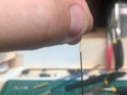
I install only the smaller guide (the small wheel) first. I then make a small needle by bending 0.006" wire. Rather than bending it against the edge of the needle holders, I use them to hold the wire and bend it free-form to make it as small a hook as possible.
Custom Finishing Models (order direct)
147 ALCO Handbrake Chain Guide
336 BARCO Steam Heat/Trainline Hoses
Detail Associates (find on eBay)
2210 Safety Chain - Black, 40 links/inch


Looking really good! I wonder if those are some type of oiling cup. Looks like they are both above the trucks, maybe to oil the truck pivot? Just throwing ideas out there.
ReplyDeleteRichard
Thanks! That could be. Part of me just models what I see, but I am interested if for no other reason I can call them what they actually are.
ReplyDeleteThanks Randy, that's great!
ReplyDeleteYou're welcome!
ReplyDeleteReally nice work Randy. Now I know exactly how to work on the RS-2s. Have you considered publishing this series in the Speedwitch?
ReplyDeleteI found a link to a photo of New Haven RS-3 561 posted in a thread on signal boxes on the NHRHTA forum here: https://www.flickr.com/photos/alcomike/20553711266/
ReplyDeleteIt looks like the mystery part may also be on the New Haven RS-3s as well??