On Monday I posted a photo of a T&P flat car and noted that it's very similar, but not identical to the Tichy flat car model.
This kit is a very well designed kit that's a good introduction to a more craftsman style kit. The design also makes it easy to modify the kit for other prototypes. Since I have several of the kits on my shelf, I figured I'd make the major modifications to show how I would go about it.
The deck on the model measures out at 39'-10". The deck boards on the model are 6" wide. To simplify we can group the cars by roughly 6" increments:
- 40'-9" to 40'-10" - NC&StL and DL&W - base kit
- 41'-9" - SP&S - 12" or two boards longer than the kit
- 42'-2" - CN and CP - 15" or about 3 boards longer
- 42'-10" - SSW and T&P - 2' or about 4 boards longer
The kit consists of a deck, separate bolsters and underframe, side and end sills, plus detail parts, including the stake pockets. The fact that the side sills, stake pockets, and underframe components are all separate parts is what makes it possible to alter the kit with relatively little effort.
I have three kits on the shelf, plus parts of another, so based on the roster info I'll build one as is, for a DL&W car, and lengthen two others, for a CN car since they had the largest roster, and T&P since that's what started this (with a photo on the NH).
The first thing I do is cut the deck in half. It's 66 boards long, so the groove between the two center boards makes this easy.
I then cut extra boards from the spare deck that I have. In this case, it was a partially finished model I picked up some place, and it's already painted. That works well for this post.
Using a True Sander, I square everything up.
The spare deck was also cut in half first, because I want the center pieces, not the portion from the bolster to the end. I squared the end prior to cutting the extra boards off, and then use one of the squared decks to hold the smaller piece against the sander. This ensures that only one edge needs to be trued up at a time.
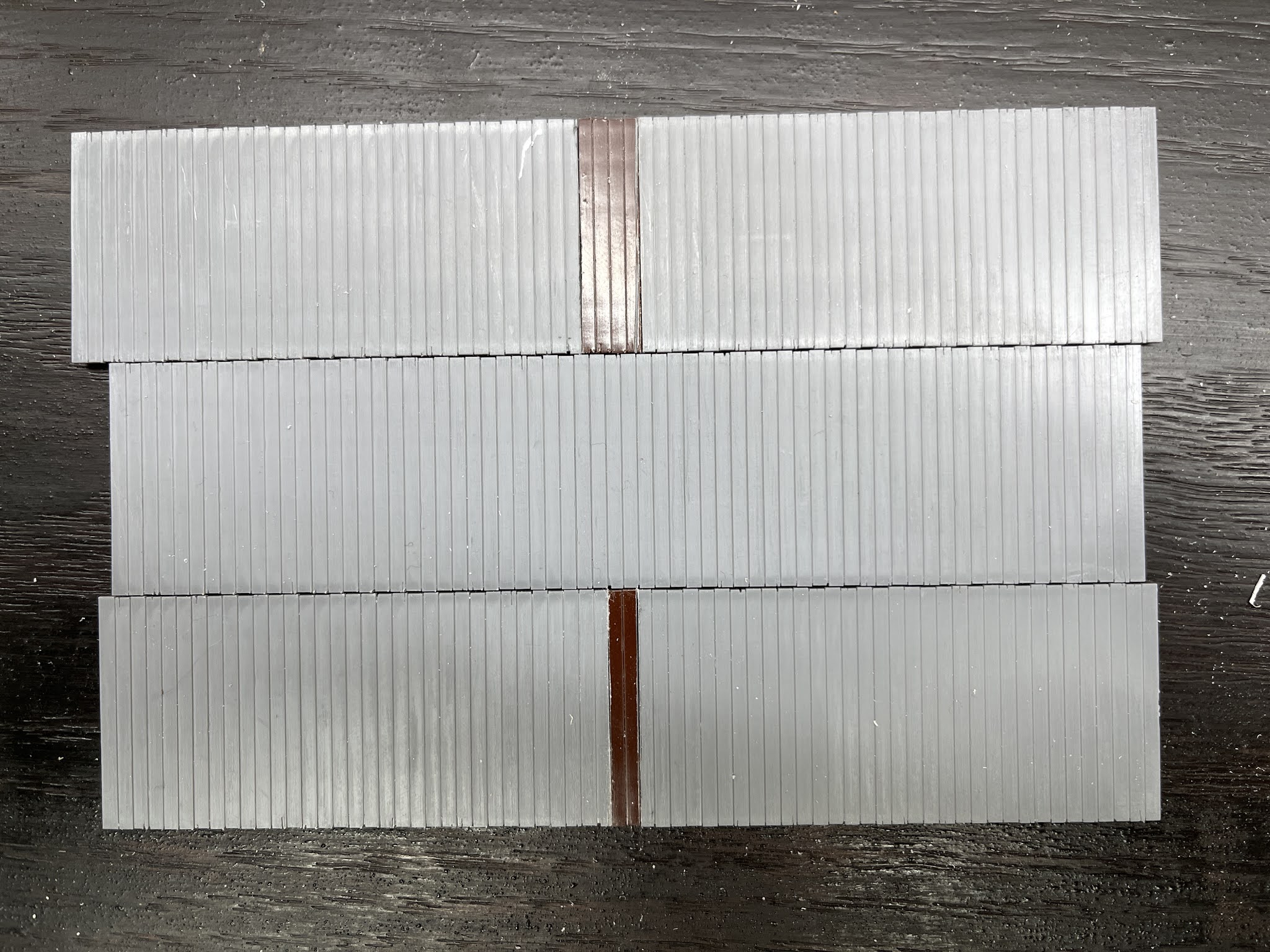
For the example, I cut a two board section in addition to three and four boards. An unmodified deck is in the center, a two board extension on the bottom, and four at the top.
These are the three that I'll be working with: unmodified, extended by three, and four boards.
Using a straight edge, I use liquid styrene cement to glue it all together. The piece of scrap brass just keeps any seepage off of the desk. I apply pressure from both ends and toward the straight edge, plus press down toward the desk to ensure it will be flat and square. Once it cures, I flip it over and apply some cement to the seems along the top and edge as well.
While they were drying, I de-sprued most of the parts, and then started the underframe. I orient the parts the same way the instructions picture. And yes, this is one of those kits where the instructions are essential. In this kit, there are some parts that are very similar, such as the three brake levers. The instructions identify them by number, but the number for these parts is on the sprue itself. So I took a picture so I could identify them after they were off the sprue.
Here's the side of the underframe that receives the brake cylinder bracket.
I find it easier to attach as many of the detail parts as possible, however with this kit there is a catch, so read on before you assemble anything to see if you might want to do it differently...
I glued the rodding (cut long) to the brake levers using CA.
I like to do this for several reasons. First, it's easier to do here then under the assembled car. It also gives me a "handle" when working with the part, and it makes the part much bigger, and harder to lose (I still lost one...).
If the small parts are still too fiddly for you, you can also attach the wire while they are still on the sprue:
I did have to cut the sprue apart in key points to get the third one, since it points toward it. I continued assembling parts per the instructions for all three models. Wetting the slot with cement then installing the lever worked well, since it softened the plastic slightly. I then applied a little more cement to the joint from the back.
I tried a couple of methods of assembling the underframe components. There are two spacers that go near the end, plus the four crossties. Of the three approaches I used, I found installing the two crossties farthest from the center and gluing them first, then the two center crossties, and then spreading the end enough to slide in the spacer to easiest. The two center crossties are a much looser fit. I chose not to install a trainline, since it won't be visible, and I haven't done the brake appliances yet either.
I installed the bolsters prior to the center sill.
Another tip - the center sill is centered between a strip of rivets, and not up against either of the stringers. I found it better to ensure that the crossties and crossbearers were lined up properly side-to-side to center the sill. For the two models that have been lengthened, the center sill will no longer reach the bolsters. So you'll want to make sure that it is centered end-to-end as well.
So you may have wondered why they made the brake levers several separate parts, since they are so tiny. The kit is designed with a weight that fits inside the center sill. The two crossbearers hold the weight in place. And that's the catch...the crossbearers have slots for the brake rodding. I found it possible to insert the rodding into the slots and slide them up to the proper location. I did break off one rod which had to be re-glued. Overall this approach worked for me, but you might find installing the rodding after the crossbearers are installed easier for you.
I installed the kit coupler boxes on two of the models, and then thought that perhaps Kadee ones would be better. The coupler cover for the kit one also forms the portion of the center sill between the bolster and the coupler box (draft gear), but it's glued on.
I usually use the Kadee boxes that have a cover that snaps on, so still no screw but that's better for a flat car.
To ensure it fits properly, I cut off the flange around the top and bottom:
Here's what they look like with trucks so far.
Without the side sills, the place you can see the difference in the length the most is the relationship between the crossties and the trucks. (You can also spot a mistake if you look carefully).
Although there isn't any risk of me completing the cars right away since I don't have any decals, I will cover what to do about the side sills, since that's where the most changes will be made.


Very cool kitbashes. Looking forward to seeing them built up.
ReplyDeleteThanks! More to come, it has been a fun little project.
ReplyDeleteThanks for sharing the article.
ReplyDeleteVery cool kitbashes. Looking forward to seeing them built up and painted. Have you done any of the New Haven cars?
ReplyDeleteWhile I haven't finished them yet, I do go over the modifications I've been making to do the New Haven cars in Parts IV, V and VI:
Deletehttps://blog.newbritainstation.com/2021/04/modifying-tichy-flat-car-part-iv.html
https://blog.newbritainstation.com/2021/04/modifying-tichy-flat-car-part-v.html
https://blog.newbritainstation.com/2021/04/modifying-tichy-flat-car-part-vi.html