Sunday, May 22, 2022

Visiting an Old Friend

A couple of weeks ago we ran a test session on Bill's new layout. I'm terrible at taking photos while doing things, since I'm more interested in being in the moment. But we had a great time, and it's a lot of fun working the different jobs so we can help Bill fine tune the operations.

However, since I arrived a little early, I did take some photos a couple of days later when Bill and I went to Bruce's house for an inaugural test session there on his layout. What makes it special is that Bruce's layout is actually Bill's old layout.

It was nine years ago (!) that we dismantled Bill's O&W layout that was in an upstairs bedroom. I don't remember exactly when, but our last ops session would have been shortly before that. Since then, we've been helping Bruce reassemble it in his basement. Long time readers may be familiar with how much of an influence Bill and this layout has had on my modeling. I cover it in more detail in this clinic.

What's most interesting is that it feels both like the same layout, but also like a new layout. Since the decks are no longer stacked, it opens up the scenes in a different way. And Bruce's additions to tie them together, plus an additional freelance town yard, also add operational options that we didn't have in the past. I started pulling out of staging into the new yard so do some quick switching first, then run through the entire layout. There were a few hiccups but overall, it worked well. This is where it really felt new, with a through train that no longer had to traverse a helix.

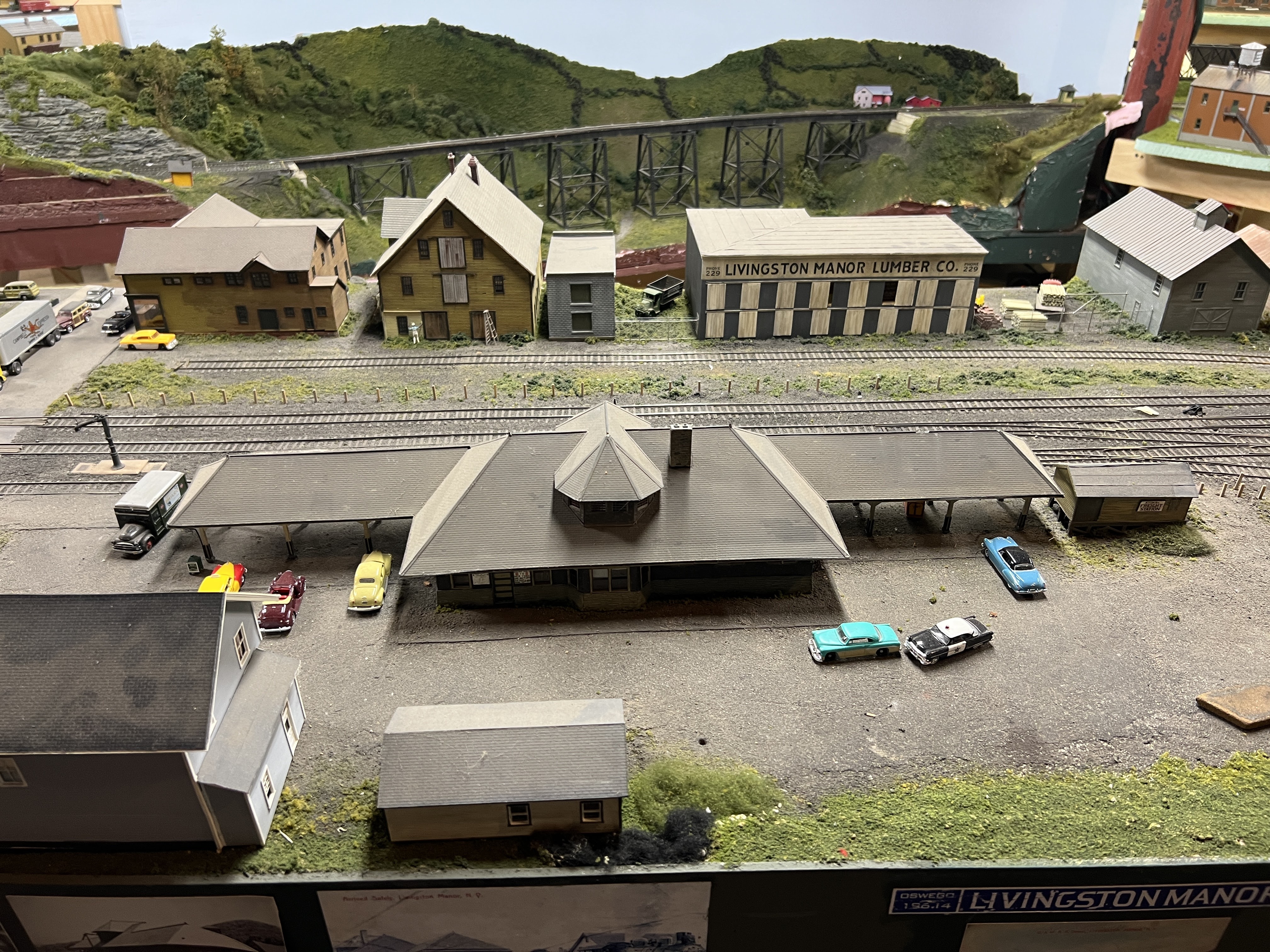
After that I ran the Roscoe local, and that felt just like old times - switching in Roscoe, plus a little in Livingston Manor. Once you're focused on the actual work, whether there was another deck above the town didn't really matter.

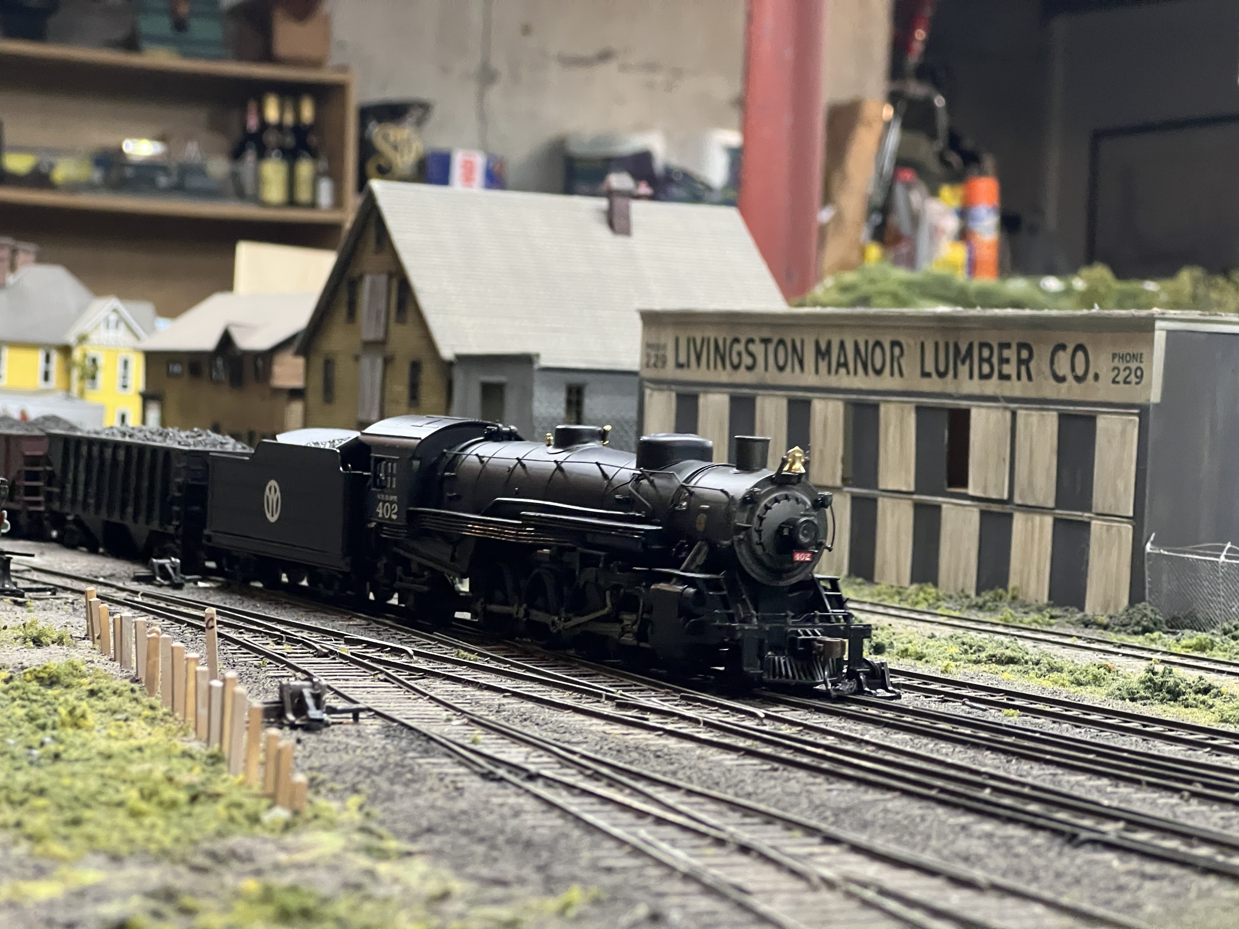
The biggest change is that Bruce is running mostly steam. Because of the helix and the tight curves to accommodate the small room, Bill hadn't designed the original layout for steam. Bruce was able broaden the curves and has made some additional modifications to the track arrangements to accommodate this.

It was enormously fun to be running on this layout with good friends (and a few good beers). It was like visiting an old friend that you haven't seen in years, and I'm looking forward to when Bruce is ready to host regular sessions.

Livingston Manor


Roscoe


The new yard.


Sunday, May 1, 2022

Walthers Heavyweights on 24" Radius

My main track minimum radius is 26" and 28" radius. When I first got the Walthers parlor cars for the 600-series conversion, which note on the package that they will navigate 24" radius curves, I was surprised to find that they didn't even like the 26" radius. They would get hung up because something is rubbing on the underframe, or occasionally derail. I found that they were reliable on about a 26.5" radius, but I wasn't going to be rebuilding the helixes, so it meant figuring out how to modify the cars.

Now that I've decided to utilize the Walthers curved turnout in one location, I need to get them to work with the advertised 24" radius since that's the radius of the inner leg of those turnouts. Otherwise, lazy or not, I'll need to handlay a replacement with a proper 26" radius. However, the cars would still require some tuning to run reliably.

Restrictions to Minimum Radius

As modelers, one of the biggest restricting factors we have to deal with is space. As a result, we have to use much sharper radius curves than the prototype would. In addition, due to manufacturing limitations, many of the operational parts of are cars are overscale. Regardless, it's typically longer cars, like passenger cars, that have issues navigating our model curves.

From a design standpoint, modelers prefer broader curves because they look better, especially with longer cars. The amount of visible overhang is particularly obvious with older layout design approaches, such as waist-high benchwork where you're always looking down. In my case, the 26" radius curves on the inner main track looks acceptable since the benchwork is high, and it will be even less of an issue as structures are built. The switch that I need to be concerned about operationally is just at the entrance to the helix. It's not a very visible location and appearance is a non-issue.

There are two things that can affect what the minimum radius is. One is that the corners of the car themselves touch, and force one or the other car off the rails. This is unusual but is easy to fix by using couplers with longer shanks. These cars are designed with a coupler box that moves toward the side of the car to effectively lengthen the draw, so that's not the limiting factor.

The second, and more common, is truck swing. A car without a center sill would be able to handle very sharp radius curves, whether it looked good or not. But most cars have center sills and, as the car gets longer, that sill restricts that truck swing more.

Modifying the Cars

In this case, there are four locations where there is contact between the trucks/wheels and underbody that are contributing to the problem. Since I don't want to remove the center sill above the truck entirely (leaving an unsightly open gap that's visible from the side), how much more swing we can get is limited.

The backs of the wheels (circled) touch the center sill just before the brake beam (arrow) does.

You can also see that the mounting screw is offset. This offset increases the truck swing against the center sill. Relocating the mounting hole to the center of the truck would help, but is a much more involved solution and thankfully we don't have to do that here.


The wheels can also touch the plastic centering springs on the extended coupler box.


The tricky one is that inner truck assembly screws can also hit the center sill, even though there is a notch designed to accommodate them.


Here we can see the notch that is cut in the center parts, and also the portion that is molded into the underframe as part of the bolster. The arrow points to the plastic centering spring.


The centering spring is a simple matter of cutting them off. These cars will always be coupled in their consists, so there is no need to worry about them self-centering. Furthermore, I don't mind manually centering a coupler on a car if needed anyway.


I measured the center sill to just beyond the truck and shaved off the flange along the top. There's no need to remove anything else, the center sill itself allows enough truck swing. These flanges are what the wheels/brake beam can hit. Once painted, this (lack of) flange is virtually invisible when viewing from the side.


I used a Dremel to make the notch for the screws deeper. I left the center portion so there won't be a visible gap from the side.

Other folks have also filed any burrs off the screw, so I did that too. 


It only takes a matter of a few minutes, none of the modifications are visible when viewing the car from the side when on the track, and they very reliably handle 24" radius curves now.