Showing posts with label Layout Design. Show all posts

Wednesday, July 12, 2023

Designing and Updating Staging

Over time I had added additional staging/storage tracks where I had space. The primary purpose for these is to store locomotives when they are not in use during a session. As I've been preparing the layout for signaling, it occurred to me that it would be useful to minimize the number of turnouts on the signaled track. 

There were seven turnouts to staging/storage tracks along the run-through staging track, but by reconfiguring the arrangement, I can reduce that to two. While these weren't in my original staging design, they were dead space and I decided it would be useful to have storage tracks where locomotives not used during the session could remain on the layout. 

On this side I'll eliminate one turnout on the main, and the second one is moved to a new location. This will create a "lower staging yard" of four short tracks for the RDCs - three long enough for a pair, and the fourth for a single unit. For 1953 sessions, these trains can operate right out of this location. As usual on my layout, they terminate in the same track as they originate.

An additional two tracks will go around behind the Agents desk and will be on a grade. That's fine, because it's storage for locomotives. This replaces the turnout that is currently back there to access these tracks. They will be long enough for the A-B-A and A-B-B-A sets of FA-1/FB-2 locomotives.


I have a general idea of how I think I can fit this using Microengineering Yard Ladder turnouts. I did pick up an extra middle turnout (you can see it in the lower right) but came to the conclusion that it wouldn't fit.

If this were for a scenicked portion of the layout, I would have modified the regular No. 5 or No. 6 Microengineering turnouts so I could curve them to follow the main, but in this case a straight ladder is fine...provided I can get reasonable radius curves to enter and exit.


I have a further two yard ladder turnouts to fit at the far end, so I mock up some ideas there too. I've tried drawing things out like this, and spent some time in the past with some of the CAD programs designed for model railroads but have found that nothing is as good as just working with track, for me. In part because as I see where things lie, I see other options and can tweak the concept instantly.


I had some cork sheets left over from making the cork board at the Agent's desk and they were the correct thickness so I used those as the roadbed and started connecting track. I'm shooting for a minimum of 26" radius here, but 24" will work just fine if I have to do that. 


This process involves ensuring that the tracks not only fit for this section, but that I'll have enough clearance at the far end for the curve to the second part. At this point, it looks pretty good.


Of course, prior to gluing it down I want to test it with the RDCs too in order to make sure they are long enough.


Looking around the corner, I've switched to Woodland Scenics foam roadbed sheets, since that's what Roger had in stock, and also their 2% grade starters to get up to the higher benchwork as it goes around the corner. 


I have a window cut out in the utility room to access behind the Agent's desk. I need to fill in the track where I removed the turnout - easily accessible but hidden while operating from the layout room. Locomotives can be stored here from the clearance point of the turnout, and I took care (using 85' passenger cars) to ensure clearance around the corner of the desk and between the tracks. The main line track will run along the edge of the cork roadbed, and I can move it further out if needed, to ensure the storage tracks won't interfere with operations.


On the other side, I've already moved the main line turnouts. Like the other side, I had HO scale cork roadbed in the original track arrangement. I found it easier to rip that all out and use the foam sheets instead.

To make this side work, I have a couple of Walthers curved turnouts, one curved Peco, and the rest standard Microengineering ones that I had on hand. I've tried a number of configurations and landed on this. It eliminates 4 main line turnouts.


One track will be sized specifically for the Comet and another track for spare cabooses. That will leave two longer tracks for storage of diesel locomotives not in use. The track through the ladder goes to the Walthers turntable used to turn locomotives during the session. I went with the Walthers one because the controller has a button that will turn the bridge 180 degrees, which is really all I need it for. But I will have room to make storage tracks for the steam locomotives when the time comes.

I used insulated joiners to isolate these storage tracks, and may also add switches so I can turn them off during sessions. 


Monday, September 13, 2021

Light

 The main room is done:


The staging lights are turned off here. It is super bright. There are slight shadows in the corners, but these really only show up in photos, not when you're standing there in person.


This is looking over a car, with my arms and the camera between the lights, on the track farthest from the front of the layout. Visibility is amazing.


Here's another angle of the same cars. You can see a bit of shadow, but not much. It's most prominent on the wall behind the Landers mock-up.

The lights are LED troffers for a drop ceiling from Amazon (the 2'x4' units in this section) and Home Depot (the 2'x2' in this section). They are 9000 and 4900 lumens, both 5000k. They are also dimmable, and I'll see what that looks like after installing the dimmer tomorrow. There are six 2'x4' and six 2'x2' lights in this section, arranged in a simple rectangle. There will be two over the Stanley/Berlin Line, and two over Whiting St Yard.


Because they are "daylight" (5000k) the layout looks very different than before. It really brightens things up, and not just because there is more light.


I've been experimenting with different color grass tufts, which is much more noticeable now.

It also doesn't matter what angle I use to take pictures anymore. 


The rest of the basement will be finished tomorrow, including dimmers. Getting this done has been a big part of preparing to move forward on other projects since I didn't want to worry about working on the ceiling this extensively after completing some of those other ones.


Monday, August 30, 2021

Options for New Haven Switching Layouts

There have been several folks recently looking for help identifying a location for a small urban New Haven layout. While it is relatively easy to find a location that is interesting to model based on industries and scenery, what I think is often missed is operational interest.


DEY-4 (GE 44-tonner) 0806 Builders Photo
It's a switcher that makes a small switching layout possible.

My first layout was based on Bill Schneider's who modeled two towns along the O&W. The local freight would work each town, and another crew could run the various through freights and passenger trains. It was a very fun layout to operate, and kept us busy for several hours at a time.

I picked Windsor Locks and Thompsonville, with the CT River bridge between the two for my first attempt. Looking back, it would have operated similarly. The local crew would switch out the two towns, with loads of long passenger trains and a couple of freights passing through while they did. But there wasn't nearly as much industry to work along the way as there was on Bill's and, more importantly, with a single level I couldn't possibly create enough staging for the frequent long passenger trains on the Springfield line. So I looked elsewhere.

I lucked out when I picked New Britain. This isn't the only way to build a small layout, or even a small switching layout, but I think there are some key factors that make New Britain a perfect city for this type of  design. And I'm pretty sure there are other similar locations on the New Haven.

Small Switching Layout Features

1. Operations are localized. This is the biggest factor that I think makes this layout work well. New Britain has two locally assigned switchers, and Stanley Works has another. This is perfect for a small switching layout, since it keeps three crews operating on the layout for an entire session. 

Compare this to a single town without locally assigned switchers. Through trains come into the layout, may drop off or pick up some cars or, if passenger, make a station stop. Then they continue back off the layout. A local freight comes in at some point, and does all the switching in town, and then the session is over. Sure, it probably comes back through town later in the day, but that could be hours later.

An alternative is a locale where multiple trains meet. Middletown on the Valley Line, or Plainville on the Highland Line are like this. Several trains come into town. One of them does the local switching, but all of them exchange some cars before heading back off layout. Plainville also has some through freights and passenger service, which would keep the crews that don't handle the local work busy for the session.

2. It's not on a major mainline. There are many locations that have locally assigned switchers and small yards. Ansonia and Meriden are two that come to mind. But the mainline traffic is extensive. Sure, Chris has proven that it can be done in a small space. With New Britain on a branch line, though, traffic is not only more manageable, but the passenger trains are shorter too.

3. Variety of industries. There are very large ones, and lots of smaller ones. The only types of cars that aren't likely to show up in New Britain are stock cars. 

4. There's a good blend of traffic. There's daytime freights and passenger service. The freights provide work during the session, dropping off more cars in the morning, then picking them up in the afternoon/evening. So the crews break down and build cuts of cars like they would at a major classification yard, but without needing all that real estate.

5. It's at a junction. This provides some operational interest, but also more connections to the rest of the world. Yes, it complicates design and staging a bit. This isn't essential, but it's a nice addition. A junction that interchanges with another road would be even more interesting.  

These factors all work very well for a small industrial layout, and ensure that there are plenty of operations for a reasonably sized crew.

Because it's a single city/town, I can build it closer to scale. On a layout where New Britain is just one of several towns on a main line, it would have to be heavily compressed. Chris picked the right kind of branch line to model for a focus on a local freight. He only had to make significant compromises in Middletown, and even then it feels and operates like it should. The other towns are all small, but they were on the prototype too. But for a location that is large enough to warrant locally assigned switchers, reducing the layout allows me to better model all of the railroad activity in the area.

It can also be economical because you often won't need as many locomotives. In fact, if I chose to model only 1953, all I would need are three switchers and a few RDCs.

Where to Start

Research, of course. There are several documents that are helpful in identifying where a good amount of operations is to be found, and then narrow it down to areas that are more manageable to model.

  • Employee Timetables. There's a page that conveniently lists all of the locations on the New Haven that have yard limits. It also provides all of the passenger schedules so we can see what's going to be running through the layout.
  • Freight Schedules. We can also look at where local freights originate and work. This provides additional operational interest, as the crews can assemble outbound trains, and breakdown inbound ones. It also provides the through train schedules. Julian Erceg has an excellent site that includes a number of New Haven ones.
  • Engine Assignment Books. We can look at where switchers are assigned. Not all yards have locally assigned switchers, but they provide session-long operations. These switchers handle all the switching within yard limits. Of the three, this is probably the most important starting point for this type of layout. Fortunately, Charlie Dunn posted all of the engine assignment books we've been able to dig up on the NHRHTA forum.

Small Towns on the NH with Locally Assigned Switchers

These are all small towns on the New Haven that aren't on a major mainline (Shoreline or Springfield Line) and have a locally assigned switcher in 1949.

  • Armory - 0975 - connects to B&A in Springfield
  • Danbury - 0942, 0954 - Joe Smith's blog covers Danbury extensively
  • Holyoke - 0950, 0957 - Interchange with B&M
  • New Britain - 0802, 0812
  • Norwich - 0814 - Interchange with CV
  • Putnam - 0804, 0969 - Shoreliner 28.1, 28.1, 33.3
  • Willimantic - 0940 - Interchange with CV
  • Woonsocket - 0801
  • Brockton - 0803 - Shoreliner 42.1, 42.2
  • South Braintree - 0922 - Shoreliner 36.4
  • Fall River - 0816 - Shoreliner 34.3
  • Taunton - 0815 - Shoreliner 30.3
Prior to dieselization, locations that received 44-tonners would most likely have had T-2-b (0-6-0) switchers, and some or all of the ones with S-1 switchers had Y-3 or Y-4 0-8-0 switchers. 
In addition, there are two industrial railroads that were independently operated subsidiaries of the New Haven. These are harder to model due to motive power prior to the dieselization dates given below.
  • Manufacturers Railroad (New Haven) - 0812 - Shoreliner 12.3, 38.3
  • Seaview Avenue Railroad (Bridgeport) - 0816 (1952), 0801 (1954) - Shoreliner 12.3
  • Union Freight Railroad (Boston) - 0600, 0601 (1954) - Shoreliner 34.1
John Pryke, of course, modeled the Union Freight on part of his layout. Union Freight had 44-tonners for a few years prior to the NH DEY-5 (S-2) locomotives. All of these could be modeled with the NH mainline entirely off-layout.

Another possibility that is geographically much smaller than its importance is Bay Ridge Yard in Brooklyn. There's lots of street running, and the car float operation from the Pennsylvania Railroad in Greenville. Car floats, of course, make a perfect visible staging yard for a layout. This is covered along with all of the NYC freight operations in Shoreliner 33.2 and 33.3.

Like New Britain, these all have enough traffic to warrant a switcher, and sometimes more, with plenty of operations that occur in a relatively small geographical area. Other than New Britain, I haven't done a whole lot of research on most of these locations. Another enterprising New Haven modeler can take up that task!

I would love to see prototypically accurate models of any of these locations. 

Friday, August 27, 2021

Layout Design/Construction - Skirting Take II

 For some time I've had some banquet table skirting along the base of the layout, below staging. This was a very affordable option, with 14' costing about $20-$25 at Amazon. It is primarily made 28" tall or so, or the height of a table. It can be purchased elsewhere in taller lengths, but for significantly more money.

Because this wasn't tall enough, I added hinged fascias from Masonite, so I could access the top shelf in the storage and this worked well enough. But I've always found getting to stuff below the skirting a bit annoying. I planned on cutting it in strategic places to make it easier, but that would also require some sewing work as well. I covered this in more detail in this post.

I'm not sure why I didn't think of this myself, but Dale told me about a Paul Dolkos article about making removable beadboard sections. Doh! It's brilliant. And simple.

Some masonite, cheap beadboard and moldings, wood glue and spray paint, and voila!


They are form fit, and can easily be removed when I need access to the shelves.


I'll stain the legs that support the upper section. You can see that it sticks up above the level of the staging tracks by several inches, also preventing things from falling. It really finishes up the room beautifully, and carries the design of the agent's desk around the room now.

Wednesday, June 9, 2021

Organizing - Paints

 One of the things that's often forgotten in layout design is storage. Yes, most have storage under the layout, but good storage requires some thought and design. I'm used to this since we live in a fairly small house, but once you start filling the basement with a layout you also eliminate a lot of potential storage.

In addition to below the layout, there is also useable space on the walls above staging. It's also conveniently well lit, and is perfect for small items like paint.

Since I had previously determined that storing Vallejo paints upside down was not a good approach, I picked up some shelves designed for nail polish:


They were inexpensive, and since they are relatively deep they fit a number of different types of paint bottles. They are also deep enough to fit two Vallejo/AK Interactive/MIG 17 ml bottles, so when I'm running low and order a fresh bottle of a color there is room for that without taking more horizontal space.

The next question was what order should I store them. If you're not familiar with Vallejo, AK Interactive, or similar paints, each is assigned a number. For example, 70.819 is Iraqi Sand, and 70.822 is German C(amouflage) Black Brown. The colors aren't numbered in a color order. In other words, there isn't a block that is all greens. I could organize them by colors, but I decided numerically will work best because I note the number in my lists for mixing formulas, or which color I used for a particular project. So it will be easier to find that way. In addition, it's easier for quickly checking if I have a particular color.

I didn't want all of the paint stored at the desk itself, primarily for appearances since it's the Agent's desk too.

I'll need more shelves. I could easily fit a middle row, but for now wanted the space for taller bottles. Now that I've tested them, I'll get enough for the entire wall. I'm estimating that with two rows I'll be able to fit about 344 bottles of paint. A third row would add another 172, but I don't think I'll need that...yet.

Monday, May 17, 2021

Design - Greg's Layout

Dick and to a lesser degree I, among others, have been helping Greg design and build his layout. The space is relatively small, and complicated by the location of the mechanicals in the room.

Greg has built the Milwaukee Everett St. Station and train sheds (they look awesome) and owns four different versions of the Hiawatha, so that is a big part of the layout, but also wants to include New Lisbon, WI, which is somewhere between 150 and 200 miles away. He'd also like to be able to have some sort of operations so he can have folks over to run it.

It sounds like a very interesting concept for a layout.

He has a roughly 22' by 14' room to work with. However, the mechanicals are located in a position that means the main portion of the layout really has 11' by 14' to work with. While we can fit some things around the mechanicals, it greatly limits options. Oh, and it has to be single level with continuous running.

For a prototype-focused modeler like me, this is a challenge to wrap my head around, and from a layout design perspective a seemingly impossible task in the space and restrictions given.

Layout Design

When starting from scratch, my approach is usually to sketch out how to maximize the benchwork in the room. I start with a minimum 30" aisles, and assume up to 30" deep benchwork and start from there. It just helps me visualize where we can actually put track.

I did some early sketches to see what we could do with a helix. Although I'd prefer to see the trains as much as possible, I am a fan of a using helix to create distance between scenes where it makes sense, and it certainly would make sense here. Dick even drew one up with a helix around the mechanicals. But Greg wants to keep it to a single level, so those are out.

In this case, there isn't enough room for a peninsula with a loop, so it's pretty much a rectangle around the main part of the room. 

The next thing to consider is where the desired key scenes will fit on that benchwork. Greg had already worked out a concept with the Everett St. Station against the 14' foot back (south) wall, which is logical. He hopes to have some industry to operate, and then back across the room with something representing New Lisbon.

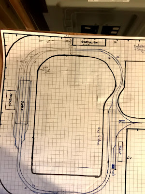
Although not the best picture of it, this is one of Greg's sketches. The rectangle at the top is the electrical box. Dick designed a swing out here to allow access, and benchwork has been built along the three walls so far. The rectangle in the lower right corner is where the mechanicals are located. 

The S-curve between the electrical box and New Lisbon also happens to be where a lift-up/out or some other approach to provide access is needed. This doesn't show any sort of staging at this point, although there is room along both sides of the room off to the right. 

The wye is going to be the biggest challenge, and I don't trust my drawing/math to know that I can get it right on paper. So we mocked up the wye with the Peco turnouts he's using, and 24" radius for the legs since we can't reasonably go any tighter than that. The goal would be greater. I have a few pieces of 24" sectional track that I use for mockups like this so I know that we are working with a true radius rather than an unintentionally optimistic one that I bend from flex track.

With our measurements, we determined that there are only three places it would fit. Right where it is, moved to the lower right corner of that section of the room so the stem of the wye goes down the other side of the mechanicals, or by moving New Lisbon to the other (right) side of the mechanicals altogether and turning it so the leg of the wye is in the same location, but facing the other direction.

Operations

But the other thing that I'm always mulling over is how the layout will be operated. This is partially a question of the movement of trains, but also where the operators will be, how they'll move through the space, and how best to maintain the illusion of a real railroad, rather than one just built in your basement.

There is an important question that I find is often forgotten as we design a layout:

What will the operators do while operating?

We often focus on the track arrangement, and maybe the specific trains, and even ensuring you have space (wide enough aisles) for people, but we often don't think about what those people will be doing for 3-4 hours or more. 

I think most of us are used to the approach of following the train for ops sessions nowadays. Each operator/crew is assigned a train, runs it through its job, and then takes another train out if there's time. Chris' Valley and Air Line locals are great examples of this.

My layout, on the other hand, is more of a switching layout. Yes, there are through trains, but they are on the layout for only a few minutes as they come up from staging, stop at the station (or drop off/pick up a cut of cars), and then go right back to staging.

Chris had to contend with that very question after the fact, like so many of us do.

Both Valley and the Air Line locals both occupy a crew for a full session. But there's another local that serves two industries in Saybrook, plus interchanges cars with the south end Valley Local. That only occupies a crew for an hour at most. What would that crew do for the rest of the time?

But by adding in the heavy passenger and through freight traffic, another crew (split between the two staging yards) are also busy for an entire session and can handle that short switching job.

For Greg's layout, the answer for me was a 1941 Trains article on the amount of activity in New Lisbon that Greg had. It covers less than two hours of (very) busy activity, but I later found some timetables to verify that there would be a good amount of activity during the entire session.

The article about New Lisbon details how two through freights both stop in town, uncouple from their cut of cars to get coal and water, and then move their cuts into a siding to wait.

In addition, two passenger trains also come into town, get coal and water, and then back into two stub sidings and wait.

Two Hiawatha trains (100 and 101) then come into town, make their station stop, get coal and water, and then continue. The other four waiting trains then start to go on their way. 

In other words, it's a perfect arrangement for a railfan style layout similar to Chris' Saybrook scene where the trains enter from and exit to staging, and the operators are in a single location handling the movements of all of the trains. The Everett St Station scene also lends itself to this sort of operations, with lots of passenger (and freight) passing through, and a little passenger switching.

The connecting track between the two, when scenicked, can act as hidden staging to supplement additional staging. A train leaving New Lisbon can pull out of the scene and stop, and at some later point the Milwaukee crew acquires it and pulls it into the station.

By moving New Lisbon to the other side of the mechanicals, it also gives us room to build an industrial area on the west end of Milwaukee.

This all goes back to answer the question too - what will the operators do?

  • Crew #1 operates Everett St. Station and all trains, including passenger switching.
  • Crew #2 operates New Lisbon and all trains, including getting coal and water.

Both of these jobs are full session jobs.

  • We can also add Crew #3 that runs a switcher handling industries in Milwaukee.

Now we've got something to work with. Six crew members, all working in their own independent physical spaces, all with full session jobs. The distance between New Lisbon and Milwaukee feels prototypical, since you don't follow a train from one to another. In fact, the New Lisbon crew won't have any direct observation of what's going on in Milwaukee or vise versa. Other than keeping train lengths down, the scenes can be built and operated fairly prototypically and should be recognizable to anybody that knows the locations.

So I sketched up New Lisbon and while it will be tight with a few compromises, it will fit. The turnouts/crossovers may not be in those exact locations, but I tried to keep all of the important tracks for operational purposes.

Note that this is rotated 90 degrees to the right from the prior photo. The lift up/out will be a simple rectangular piece. Additional staging can be built to be semi-hidden on the left side of the Milwaukee and New Lisbon scenes, and also on the right hand side if needed. There will be a slight grade down to New Lisbon, and a grade up to the industrial area to allow the staging on the north end of the wye to go under that section to be hidden.

This uses 26" and 28" radii for the main tracks, and although they won't be exactly parallel, also for the station stub tracks where they will need to curve. In addition, the legs of the wye are 26" radius.

As you can see, the wye ends up about 30" away from the mechanicals, but anything else eliminates any possibility of modeling the station area itself, and to maintain the radii prevents it from moving any further to the right. All sidings, stub tracks, and staging tracks are at least 3 feet (one piece of flex track) long. That's quite short for passenger trains, but it's about the best we can do here. The only thing that's really missing is the dead straight trackage through town, and that's just unavoidable in this space.

The New Lisbon scene is a good example of how the track layout is crucial if you want to replicate the prototypical operations. With six trains meeting at the same location, and all getting coal and water while making their stops, you have to have at least four tracks long enough to move trains off of the main. Fortunately, two of them were stub tracks, which adds interest since you need to back passenger trains into both of them. There is a coaling tower at each end of town, one of which was built specifically for the westbound Hiawatha.

The Everett St. scene is at the top of the page (not drawn, obviously), and the peninsula in the middle will be an industrial location with lots of work.

This is just a sketch and recommendation, and as it's Greg's layout things may very well change as we help build it. But I'm pretty confident that this is the best (only?) way to fit New Lisbon into this space and we can ensure that he's able to model both of the key scenes that he'd like plus meet his goal of being able to have folks over to operate too.

Monday, January 25, 2021

Designing Operations for Paul's Layout Part IV - The Movement of Cars and Paperwork

Here's Part I, Part II, and Part III.

A lot of people like to start at this point (or at least think they are starting here). But I think that by starting where we did, the movement of the cars themselves is largely self-evident.

  • Cars come onto the New Haven via Interchange Tracks.
  • They are classified based on their destinations into trains.
  • The trains move the cars to their destinations.
  • The cars eventually get moved to an Interchange Track to leave the New Haven.

This is basically what we are attempting to design, but much of it has already been addressed:

  • Cars will enter the layout via Track No. 5.
  • Eastbound cars are bound for destinations in/beyond Boston.
  • Westbound cars are bound for destinations in/beyond New Haven.
  • Any car at an industry is bound for destinations beyond Boston/New Haven.

Movement of Trains Continued...

To start, cars move on trains (duh), so we have to define the trains. Lucky for me, Paul is modeling the New Haven, so I don't have to define anything.

From the October 28, 1962 Arranged Freight Service Symbol Book No. 14:

Boston to Cedar Hill (and points beyond)

Times are departure and arrival times for Boston/Cedar Hill

  • BG-1 (Boston to Bay Ridge) - 11.15 PM/5.05 AM
  • BH-5 (Boston to Harlem River) - 8.15 PM/12.25 AM - Trailers
  • BH-7 (Boston to Harlem River) - 10.15 PM/2.00 AM - Trailers
  • BN-1 (Boston to Cedar Hill) - 3.00 AM/11.40 AM
  • A/BO-1 (Boston to Maybrook) - 5.30 PM/8.35 PM
  • BO-1 (Boston to Maybrook) - 7.00 PM/11.40 PM

Cedar Hill (and points west) to Boston

    Times are departure and arrival times for Cedar Hill/Boston

    • FGB-2 (Bay Ridge to Boston) - 3.05 PM/9.35 PM
    • GB-8 (Bay Ridge to Boston) - 8.55 PM/2.00 AM
    • HB-6 (Harlem River to Boston) - 11.09 PM/3.05 AM - Trailers
    • HB-8 (Harlem River to Boston) - 1.50 AM/5.46 AM - Trailers
    • OB-2 (Maybrook to Boston) - 7.40 PM/12.40 AM
    • OB-4 (Maybrook to Boston) - 1.00 AM/7.05 AM
    • OB-8 (Maybrook to Boston) - .10 AM/8.45 AM

    So we can name a given inbound/outbound train and schedule them sequentially for now, and can work to adhere to the schedule in the future. This will make it easier to define what we're talking about. For this session starting in Boston, I'll say it's 2:00 AM and GB-8 has just arrived on schedule, and we are building BN-1.

    You'll note that the BH/HB trains are noted as trailer trains. That would be easy enough to add by using the Interchange Track as a fiddle yard and adding/removing the trailer cars at the appropriate time in a session. Many of the trains have specific consists, for example FGB-2 is the Florida-Greenville-Boston job and typically had a lot of FGEX produce reefers. Once again, even though the scenery is the same, we'll see different consists and start to recognize the action that's taking place.

    Industries

    Let's look at the two industries. There are a few ways we can handle them.

    Option 1: Each industry is worked by a train that can switch it (i.e. is a trailing point move).

    Option 2: As option one, but westbound trains can take the reversing loop and service both industries on their run.

    Option 3: Neither train services the industries, and they are in yard limits, and served by the switching crew in the yard. They could service one or both industries during each yard scene.

    I prefer option 3, simply because through freights didn't service industries. I would also spot the cars on Track No. 2 first, then switch jobs (and even locomotive) from the yard crew classifying cars to a switching crew servicing the local industries.

    Waybills

    Any waybill system will work. Full size waybills to the 4-part car card/waybill approach. Since that's what Paul is planning on using, that's what we'll go with.

    Because this is a one-operator layout and the yard is serving double duty, we will see some of the same cars move multiple times. We can set rules for the sequence of cars to minimize that if it is something that bothers you.

    For example:

    The Interchange Track will be a fiddle yard. A car coming onto Track No. 5 must traverse the layout before being delivered to an industry, or going back to Track No. 5 to be removed from the layout.

    The session starts at Boston. NYC 12345 is on Track No. 5 and is eastbound to a destination in Maine. That will be moved to Track No. 4 (eastbound cars), but we're building a westbound train (since we're in Boston). So that will stay on Track No. 4.

    After building BN-1, it will run the layout until it arrives at Cedar Hill. After the yard is worked, FGB-2 will be heading out from Cedar Hill, and will include NYC 12345. Once FGB-2 arrives at Boston Yard, it will be switched off the train to Track No. 5, and off the layout (and the New Haven).

    An example using a 4 part waybill:

    1. Industry eastbound
    2. Interchange westbound
    3. Off-layout industry westbound
    4. Interchange eastbound

    In this example, we won't fiddle cars on/off the layout. The Waybill is flipped to the next destination when it reaches its current destination.

    The car is on Track No. 5 and we are in Boston. When pulled the waybill indicates it needs to go to Boston Siding eastbound. So it is placed on Track No. 4. A train will run, and once we are switching Cedar Hill it will be placed on an eastbound freight.

    It will arrive in Boston, and be pulled for a switching crew to deliver to the Industry. Now that it has reached its destination, the card will be flipped. The next time the industry is switched, we will see that it is going to an interchange on a westbound train.

    Once it takes a westbound train, it will be switched out to Track No. 5. That's its destination, so the card will be flipped to 3, which indicates an off-layout industry westbound. Once again a train will run the layout before Track No. 5 is pulled again, and the car is placed on the westbound track. After it returns to the yard, it will go back to Track No. 5, since that's the Interchange Track covering any location not on the layout.

    Each waybill for this layout needs a destination and a direction. Since there are only two industries, most of the cars will be destined for someplace off layout. You can enhance this with more specific destinations, such as specific industries in and around Boston, or even an industry in another town that would be serviced by a local freight originating in that yard.

    As time goes on, the more layers of prototypical information and action that you add, the more prototypical the layout will feel.

    Operational Considerations

    There will be a lot of car movements, and most of the work is classifying the inbound freights. To do this, the first step is going to be to pull Track No. 5, and classify those cars. This will empty the track, so the cars coming off of the inbound train and being spotted on Track No. 5 will not be reclassified until a train has run the entire layout again.

    I would switch out the industries after classifying the cars on Track No. 5 and the inbound train, because some of the cars from the industries could be destined for the next outbound train.

    After all of the cars, including ones pulled from industries, are classified, then the outbound train will be moved to the departure track, a caboose added to the correct end, and the road power will come from the engine house for the next run.

    Paperwork

    The fourth aspect to operations for me is paperwork. In this case, there is little I can think of in this regard that will enhance things. A time table and a more prototypical looking waybill will help immerse you in the operation of the railroad.

    Operations Make the Layout

    As should be clear, I really enjoy digging into the operations of the railroad as much as I like building and detailing a model. It's all part of the model to me. But far more modelers are still building 4' x 8' layouts and then want to add operations later on. While I think you can design a layout better suited to operations, and particularly for ops sessions, the reality is that a lot of us will remain lone wolves hiding in our basements and running our trains.

    But I also think that an operating layout is also more likely to be a long-lived layout. Or at least a life-long hobbyist. There are a lot of aspect of the hobby that can keep you busy for decades. If you like building/weathering freight cars you'll never run out of things to do. But model railroading is different than just model building in that we can run the models we build, and we can run them with a purpose. This seemingly simple layout will take an hour or longer to run a full cycle of breaking down, classifying, and building a train to run to the next terminal yard. Especially if you consider all of the aspects of actually working a railroad. Your ground crew throwing the iron, and hooking up the air, and testing the brakes, or running the locomotive at appropriate speeds and accounting for momentum, etc. DC, DCC, it doesn't matter.

    I think that's even more true for a "simple" layout like a 4' x 8' that's a loop with a yard and/or a few industries to switch. There's a lot more to a little layout like this when you consider how to operate it prototypically.

    Monday, January 18, 2021

    Designing Operations for Paul's Layout Part III - The Movement of Trains and Staging

    Here's Part I and Part II.

    What do Railroads do?

    Railroads are a shipping company. They move commodities from one place to another. 

    Well, duh, right?

    The Movement of Trains
    In my view of operations, there are four major components: The Jobs Performed by the Railroad, the Movement of Trains, the Movement of Cars, and Paperwork. As you may have guessed, a lot of folks like to start with the Movement of Cars (car cards/waybills) when designing for operations, but for me that's still to come.

    First we need to figure out how trains will be moving around the layout. To do that we need to know where we are, and what Point A and B are, and if there are any intermediate stops as well. Oh yes, and the layout is a loop.

    A digression - for decades we've seen layout plans talk about point-to-point layouts, as if they are inherently different from a layout designed as a loop. But the real point (ahem) is that a real railroad travels and moves goods and/or people between two or more points. So that means you have to design a layout with a start and and end, right? 

    But it probably didn't take long for people to realize that even in the smallest scales, we can't build the entire rail system in our basement (or laundry closet), so we'll need to find a way to include the parts we don't build. Thus the concept of staging.

    It's pretty simple - you have a layout designed with two ends, and staging at either end to represent everything else. And obviously this has absolutely nothing to do with the layouts we built as uneducated kids on a 4' x 8' loop.

    Except that my layout has a helix at either end, that goes down to the lower level where the staging is, and it also forms a complete loop. So I guess it can be a loop, but part of the loop is hidden, right?

    Why don't I just get to my point, which is:
    Point-to-point is a method of operation, and not necessarily a physical design.

    Back to my layout to clarify. If I have an open house, I can just put a train on the mainline, and let it loop through the layout for as long as I let it run. It's a loop. But when operating the layout, we consider that the right helix is heading toward Hartford, and the left is going to Plainville, and no train going down one side would ever come back up the other one.

    Yes, it's certainly possible (and often preferable) to design a physical point-to-point layout. But just because a layout is a loop doesn't mean we have to operate it that way.

    OK, back to where we were: Where are we?

    Paul labeled the left loop as New Haven and the right as Boston. I suggested an alternative. The layout is New Haven and Boston, depending on which end of the run we find your train.

    That is Point A and Point B are defined by operation, not by the physical layout. 

    You start the Session in Boston Yards, and in incoming train has arrived from New Haven, from the left loop (west). You break down the train, build a new one, and head west to New Haven.

    If you enjoy watching trains run around a loop, then you can do so for as long as you'd like. Otherwise it can be just one. In which case you have arrived at Cedar Hill, and the layout is now in New Haven.

    Some people won't like this approach, I get it. But then I'd suggest you try it. Because my modeling buddies and I have commented many times that the details don't matter when operating, because you're focused on the operations. Both Chris and I have had many ops sessions on our plywood (OSB) central layouts, and nobody has complained that the ops session was a failure because everything was the same shade of plywood (well, except Essex through East Haddam on Chris' since that's built on pink foam).

    To me, Movement of Trains also addresses things like signaling, Time Table & Train Order, etc. But those are potential layers to consider in the future. We need to get this operating for Paul first, get a handle on the basics of operating the layout before we add those layers.

    But that still doesn't address the issue of (lack of) staging or, to put it another way, the lack of connection to the outside world.

    Staging
    So let's look at staging.

    I think it's one of the most important aspects of layout design. And to design proper staging, I think you need to have a general idea of what you'll be running on the layout in terms of trains. Because you must have a staging track for each train, right?

    The answer, of course, is yes. And ideally that will be off-stage. But in a small space it may not be possible for you to have off-stage staging.

    There are three basic types of staging: hidden, visible, and fiddle.

    Hidden staging is the traditional staging, separate from the main layout, where trains await their next run. It can be a siding on the back of a loop and hidden from view. It can be in a second room, or a second level with a helix. Anyplace you can put a hidden track where a train will start or end its run is what most people think about when discussing staging.

    Visible staging is also fairly popular. A yard at one end of the layout often serves as a visible staging yard. Trains are built and broken down at the yard, which runs to the other end of the layout, sometimes another yard, or a loop that returns to the same yard. A hidden staging track or two might exist for interchange to another road, or a dummy track serves the same purpose. Another type of visible staging is an interchange track.

    Fiddle staging is a point, sometimes hidden, where trains are built and broken down. It's a real space saver, but requires you to actively swap out the cars. A carfloat operation is one possibility. You can even have multiple floats, pre-loaded, and you swap out the float itself. This can be combined with other types of staging as well. 

    An example I've provided fairly frequently when people online ask about small layout design and how much staging is needed is the CNZR. You can look at my earlier post for details on the operation, but the basic schematic is this:

    It's a small branch line that has their engine servicing at the end of their line. On the CNZR it's literally the end of the track, with a couple of sheds, and the locomotives sitting in the open. A runaround is across a street. The other end of the line consists of a runaround, and a junction with another railroad's mainline, and a couple of interchange tracks.

    If we look at it from the perspective of the crew, then they pull cars and drop them on one of the interchange tracks, and pull inbound cars from another interchange track. That, on the prototype, is visible staging. If this is wrapped around the walls of a room, you can easily add a hidden track to create a full loop for continuous running when you want it. They only have a single customer, but there's no reason why you can't add more.

    For this layout, it's all visible staging. The passenger train never leaves the layout. Freight cars can stay on the layout, or you can fiddle some of them on/off, either during or between sessions. Locomotives are on trains or being serviced, and never leave the layout. But we can still have a connection to the outside world.

    Track No. 5 is now designated as an Interchange Track.

    We've already declared Track No. 3 as westbound, and Track No. 4 as eastbound. Since we're only running one freight at a time, this helps prep everything for the next train. Which means next time we can talk about the Movement of Cars.

    Movement of Trains - Passenger Service
    We can extend the "road scene" by switching between the freight and passenger trains. Since Track No. 2 is an independent block, the passenger train can be at the station while the freight pulls into the siding. Then the passenger will proceed to the passenger station on the Coast Main Line, stop, and then proceed back to the other side. If desired, it could be stopped in the New Haven block, while the freight continues around the Boston loop, and so on.

    I would also use the reversing loop to allow the passenger train to go out, then back to meet the freight in different directions. Again, the freight can be parked temporarily in a block so the passenger crew can "turn" the train by running around their consist using Track No. 2, and being ready for another out-and-back.

    Admittedly, this is not an ideal layout for long runs, but you can have a meet or two, and some people just enjoy watching the trains run. That's possible here, but for me the bulk of the operations would be in the yard. 

    Back to the Movement of Trains
    As for how trains are moved across the road, which is what I usually focus on? There isn't really any need to worry about TT&TO, or even operational paperwork here. Signaling could be added to indicate when one of the blocks is occupied. But as a single-operator layout with a single-track mainline in DC, there's not going to be any need for anything other than, "the train I'm running has the main." 

    Having said that, we can design a schedule and we'll look at that next week.

    Monday, January 11, 2021

    Designing Operations for Paul's Layout Part II - The Jobs Performed by the Railroad

    Here's Part I.

    So, we have a simple loop and two industries to service. We can turn a train, but only one direction. And a yard. What are we going to use the yard for?


    Well, to me the yard is the key for this layout. But first a little model railroading philosophy...

    One thing you may notice when operating a layout, is that your focus is on the work in front of you. Since this is primarily going to be a single-operator layout, we can take advantage of this. This narrowed focus also narrows your view of the layout. Which is one of the reasons I like a layout to be built somewhere between chest and eye height. It draws you into the scene, and limits your view of the rest of the layout.

    We accomplish similar things with view blocks, etc., but with a small layout in the form of a loop, we'll have to rely on our imagination and narrowed focus a bit more. By doing so, we can focus on the action as a series of scenes, rather than how the relate to each other in the context of the layout itself.

    The layout is our stage. For many of us, the stage is large, with different scenery for each. In other cases, the stage is a small independent theater. The scenery is more imaginary. Implied by the action on the stage, rather than a literal depiction built by the scenery crew.

    By thinking more interpretive than literal, a small layout can represent a much bigger operation. And more we dress up the operations themselves, the less important the surrounding scenery is. 

    You'll also notice that my focus is, once again, more on the operating experience. I'm sure you can get a sense as to how this will look on the the layout when you operate it. The details, about how trains or cars are moved, or even the paperwork used, are details that are added to clarify and provide structure and prototypical 'operations scenery' to the process of operating.

    A typical approach to designing operations would be to try to jump in with car cards and waybills. And in fact, that's what Paul originally asked me to help with. "Supplies and bill boxes are already ordered from Micromark, how do I get started?" sort of thing:


    But with only two industries, that wouldn't provide a whole lot of operation. By stepping back a bit, we can let the layout design itself help inform us as to where to start with operations design.

    The Jobs Performed by the Railroad
    As I've said, my focus on designing operations is on the operating experience that the crew has when running your layout. So I like to start with the jobs they'll be performing. This is more than just a practical consideration, it also enhances the operating experience.

    In this case, we're handling a lot of different jobs. Since this is a single operator layout, all of them will be performed by the same person. But rather than lump everything together, I still like to think of them independently.

    Since the majority of the layout is a yard, we'll start by looking at the jobs in a typical terminal yard:
    • The road crew brings their train into the yard, but they do not have permission to move their locomotive within the yard facility. In fact, the railroad forbids it because they would have to pay the road crew higher rates for their entire run if they did.
    • Hostlers are responsible for taking the road power to engine servicing, and also for bringing the road power to any newly assembled train. 
    • Yard crews man the switchers that do the work classifying cars and breaking down/building trains. 
    • The Yardmaster is responsible for coordinating all the work in the yard, and the Foreman is responsible for ensuring that the work is completed as directed by the Yardmaster.
    All this is interesting, but why do I care for a single operator layout?

    Because it helps to envision the scene we're creating. It helps to provide the tunnel vision that will obscure the fact that everything is occurring sequentially since you can only do so much at one time. In a sense you are like an actor stepping out of one role and into another and, like a movie, things that happen simultaneously must be shown separately to avoid missing any of the action.

    Understanding the different jobs helps us visualize and separate those scenes into distinct events, enhancing the illusion that this is all part of a much bigger operation. It also makes it easy to operate a larger layout where you might be assigned to be a hostler, yard crew, or yardmaster. 

    Although quite condensed, this already achieves the goal of prototypical operations. You can add layers, such as how you run the trains, paperwork, etc. to enhance that experience. But for a big picture overview, think of it in a series of scenes in a movie:

    Scene 1: A road freight has arrived, and the locomotives need to go for their inspection and maintenance to prepare for the next run. Hostlers uncouple from the consist, and head to the engine house.

    Scene 1a: In the meantime, a yard crew starts classifying the inbound cars, building new trains, or shoving the cars to an interchange track to be picked up by another road.

    Scene 1b: A switching crew is handling work at several industries within yard limits.

    Scene 1c: A train is near ready for departure, and the hostlers are on their way with the road power.
    The crew is given their orders, and throw the iron just after the latest passenger train passes, and starts to pull out onto the main.

    Scene 2: The road freight is on the high iron, on its way to Cedar Hill and making good time. They'll have to take the siding at a couple of points to let the first class passenger trains pass, before pulling into the yard.

    Scene 2a: The first class passenger train is running from station-to-station, and turning at the terminal at the end of its run for the return trip.

    We're not talking about the physical scene, and how to model the landscape, structures, etc., but the action that takes place. But it relates to the physical elements as well. We need to determine where this will take place on the layout itself.

    Designating Yard Tracks

    A yard typically has a number of dedicated tracks for specific purposes. In this case, though, we'll have to use different tracks for multiple purposes. Remember that on the rear (North Main) west is left and east is right.

    Track No. 2 is a runaround for the North Main Line, but we're also going to use it as an arrival and departure track. Freight trains will terminate here, and when a train is built, we'll stage it here. When a freight arrives, the road power will be taken to the engine house, and a switching crew will break down the trains.

    Tracks No. 3-5 are the yard tracks, where cars will be classified. 

    The yard ladder also serves as the Yard Lead, along with a portion of the main line. Runaround moves will also have to use the main line. 

    The Coast Main Line is actually just part of the yard complex at this point, allowing access to the engine servicing tracks. Paul has wisely kept that in the same electrical block as the yard.

    Cabooses will have to be shoved out of the way temporarily as working. Either on one of the yard tracks, left on Track No. 2, or on Coast Main Line.

    Not ideal, but we can have a fully operational yard.

    Yards also have tracks designated for specific purposes. That is, the same outbound train is built on the same track every day. With that in mind, here's a track list:
    • Yard Ladder and North Main to the right of the ladder: Yard Lead
    • Track No. 2: Runaround, arrival, and departure track.
    • Track No. 3: Yard Track for Westbound trains.
    • Track No. 4: Yard Track for Eastbound trains.
    • Track No. 5: Yard Track
    This is all we'll need for terminating a freight, servicing power, having a switching crew break down, classify, and build new trains, and originating a new freight. Even better, this process takes quite a bit of time, and while you're operating you are ignoring the two loops at either end of the layout.

    With those designated, we can easily see how the scenes I described can occur on this layout.

    Monday, January 4, 2021

    Designing Operations for Paul's Layout Part I - Setting the Stage

    Happy New Year! 

    One of the reasons why I blog is because I figure if I've come across something that interests me, that somebody else might find it of value as well. Recently Paul, a fellow New Haven modeler in N-scale, saw one of my clinics on operations and reached out to see if I could help with setting up operations on his layout. Of course I'm happy to. This will be a short series of posts on designing operations for Paul's layout.

    This ended up being a very interesting exercise, because the layout is complete and fully scenicked. So there won't be any changes to the layout itself. They have recently downsized, so finding a place for his O-scale models was out. In the end, the best space he could find was the laundry closet. So N-scale it is.

    Here's a panorama of the entire layout:


    And a closer look in sections:


    As you can see, the layout is a dogbone, with a yard built between the two sides. There's a single industry at either end, and regardless of the direction, one is trailing point and one is facing point. There are also two tracks for an engine house.

    An initial reaction might be that there is very little to work with. A single industry to work in each direction, one runaround, and four yard tracks. I would have liked to see an actual yard lead, instead of having to use the main.

    I'm on a lot of Facebook Groups, and I see a lot of 4'x8' layouts, most of which obviously consist of one or more loops, with some industries or yard tracks in the middle. And I see a lot of other folks with the opinion that they can't be operated, or at least not prototypically. 

    While you can certainly plan ahead for a layout that will be designed specifically for operations, I'm also not going to put down somebody's efforts and layout.  Heck, my layout isn't even running right now, and I barely have any scenery after a decade of building it. Who am I to judge?

    I'd go so far to say that with a well designed operating scheme, you can make a layout feel more prototypical, even when limited to a loop in a small space. So can I design a relatively prototypical operation with this layout? I think so. I'm going to try anyway.

    Getting Started

    The first thing I needed to get a handle on here was what options we have for just running trains. The loop is what threw me, since I'm not used to working with that design. At least not since high school, and I wasn't doing any operations then.

    Obviously a train can run in either direction around the loop. It would only be able to service one of the industries, unless it uses the runaround to handle the facing point switch. Trains that start running westbound (left on the North Main Line) can service the New Haven Siding, then use the Yard Track as a reversing loop, so they can service the Boston industry.

    Next I have to get a handle of what I'm trying to design. The layout is in a closet, and it's DC. So I'm going to start with the assumption it's a single-operator layout.

    He has a few blocks so he can park trains if needed while running trains in other sections. That will provide some flexibility. We might need to create additional blocks as we operate the layout, we'll have to see. 

    He's got a passenger train, a freight train, and several additional locomotives. 

    But servicing 1-2 industries doesn't do much and would be a very short operating session. Plus, it doesn't utilize the yard much. What can we do with that?

    The Yard Lead also forms a reverse loop on the right side (labeled Boston) on the layout, but it only works in one direction. Once you've reversed the train, you can't reverse it back without a runaround move.

    Labeling the Tracks
    The only concern I have to start is that the front and back main line tracks are both labeled with east to the right. But since it's a loop, the front will be the reverse of the back. Because of the orientation of the yard, I will use the rear (North) main as the main line. So to the right on the rear track is east, to the left is west. When trains are running, the front will be the reverse. Note that I'm also eliminating the south/north designations, we'll just be talking railroad east and west.

    That should be enough to get started. Next time we'll look at what I can come up with for actual operations.

    Thursday, October 1, 2020

    Structures and Scenery - How Big?

    One of the things that I've noticed over the years is that non-railroad portions of many layouts are under scale. In particular, this tends to be the case for roads, trees, and structures. I'll address roads and trees at a later time, but let's look at structures.

    Many times structures one model railroads are undersized. This is particularly true of industrial structures such as factories. Why would this be? 

    To start with, a lot of commercial structures seem to trend towards compressed. This makes some sense, since they want to make the building capable of fitting on more layouts. Not everybody has the space for very large factory buildings, for example, and I believe the most common layout footprint may still be a 4' x 8' sheet of plywood. One or two large industries fill up a lot of space on a layout that size.

    There's nothing inherently wrong with that, but I really like the idea that sense of scale with really large industries. Particularly when modeling railroading's past, it's a reminder of the sheer scale of industry that was spawned by the industrial revolution. For example, the Stanley Works and Russell & Erwin smoke stacks.

    Of course, big industries take a lot of space. And other compromises come into play when building a model railroad. For example, if you're building a double-deck layout, the clearance can often limit how big you can go. But my general approach is to start with a scale footprint, and then make modifications from there.

    Right now I'm tweaking the corner to the east of Elm Street. New Britain Yard, between Elm and Main Streets, is modeled somewhere between 70% and 80% to scale. I haven't measured things in a while. While this seems very high, there are still compromises that must be made with even that amount of compression. We'll see what impact that has when I get to building the structures.

    But east of Elm St is worse, because the track has to curve back around to the helix. As I've noted, on the prototype this section of track is curved the opposite direction. So nothing can be in the exact place it should be.

    So how does that affect the scenery, particularly the structures? As it turns out, City Coal & Wood, later City Supply, can be modeled almost entirely to scale. The placement of some elements might be a little off, but overall it can be modeled very faithfully. 


    As you can see in this picture, I've cut out footprints of the two main buildings. These are fully to scale and will fit pretty well. Here's a reminder of the prototypical layout. Note that the coal bins, the footprint on the right, is already gone in this photo.


    So the oil tanks can be modeled, just not in the exact location. I can probably add a bit of the structures across the parking lot, which are still part of the same industry. But what's different is that Swift & Upton/New Britain Lumber Company won't be in the correct location behind it. Instead, it has to be next to it as the track curves away from the first industry on the layout,

    Furthermore, it's clear that the prototypical length of the lumber sheds won't fit at all. They would cross over the mainline, and it leaves no room for the stacks of lumber that are outside. Clearly this will have to be shortened or, more likely, run into the backdrop. 

    Fortunately, these are very straightforward and plain structures. There are no windows or loading doors, no real features that would indicate that the model is compressed. Most of the time, this is much more complicated.

    Another signature structure will be the freight house. Fortunately it looks like I'll be able to model that do scale, a full 7 1/2' in HO scale. I'm going back to the Sanborn maps to cut out scale footprints for the other structures I'll be modeling, and use that as a starting point to see what will need to be compressed for each of them as well. Part of the art of model railroading, is figuring out how to compress things without losing the character of the scene. Most of the structures are still a ways off, but it's good to revisit the plan and see how things fit together while I'm (re)finalizing the plan, gluing track down, and dropping feeders. Because after that's done I'll get to work on ground cover, roads, and ballast. Knowing the footprints of the structures will be important to get worked out before I do that.