Like getting down to the layout, time has put a crunch on posts to the blog too. I have been working on the new website, and I'm in the process of building another new site for something I can't divulge just yet. Plus work, work, and business too.
So here's a few unrelated things that are happening. First is a wonderfully windy and moody autumn morning/day following a decent amount of rain yesterday (a nor-easter apparently). I had the day off from the railroad yesterday, but apparently none of the line or construction crews were working due to the weather anyway.
The line crews were on storm duty today (and probably tomorrow) so there weren't nearly as many crews working today. I spent the day at Plainfield St. activating the signal for the hi-rail flatbed and dump truck a few times. I was also fixing a computer for Jeremy, and Dale loaned me a new book that I heard about on A Modeler's Life:
It sounded interesting on the podcast, but was way better than I even expected. I'm doing a clinic for the next Hindsight 20/20 event in December. I've decided to do a short clinic on operations, and this covers a lot of similar thematic ground and I'll be able to point folks to the book for more ideas and inspiration. I highly recommend it, and just added it to my birthday/Christmas list (I'm not allowed to buy it right now...). I'll be getting over to Dale's house in the next week or so to get some photos and videos for the clinic.
I was also able to join the weekly Modeler's Life Patreon Zoom for the first time. Talk about inspiration. Much like the blog, it provides an impetus to get something done on the layout. Feeders are the big thing, so that's my (self-imposed) homework for next week. It's time to get trains running again (which Chris reminds me pretty much every time I see him). Since the west side Highland Line is still operational, the goal is to complete the other half of Whiting St. Yard along with the Berlin Line. This is because I already have the RS-2 ready for testing the NY-4 train from Berlin (Cedar Hill) staging to Holyoke staging. It really shouldn't be more than a couple of hours of work between now and next Wednesday. We'll see how it goes!
The railings on the Proto 2000 models are very fine, and appear to be to scale. So why would I want go through the trouble of replacing them with etched parts?
This crop of 0937 taken by Ed Ozog shows the end railing matches that of the Proto 2000 model. The lower portion of the railing curves back up and attaches to the pilot above the uncoupling levers.
This arrangement was only used on the first 10 (0931-0940) New Haven DEY-3 locomotives.
On the remaining locomotives, the railing continues straight, with a right angle turn to attach to the pilot just above the step. This is visible on this crop of 0994, photographer unknown.
Otherwise, the rest of the arrangement appears the same.
So that leads me to checking out the etched parts as an alternative. But they are slightly larger stanchions than the P2k ones. In addition, they have the additional detail of the two rivets on either side of the stanchions (not just the ones that attach the stanchions to the frame). Plus, I just like trying different things and expanding my skillset.
Work has kept me pretty busy, and I haven't really gotten any more done on the S-1.
So here's a video at work, running from about mile 3.5, or the Hartford Bloomfield border just south of the cattle chute, across Cottage Grove Rd, and then along Savin Rd. past the Roger Sherman switch to about mile 4.5.
A beautiful October day on the railroad.
Here's a link in case the video doesn't show in the mobile version: https://youtu.be/WuKANfu04nE
A new tool. The packaging was impressive enough to do an unboxing:
It consists of a base, with a removable base plate, a spring that is over the post, and the knob with a nylon washer that holds the bending brake (I think that's what it's called...) to the tool. The larger one has two base plates, one like this one, and a stainless steel one with a mirror finish. I liked that it also comes with the handheld bender. That worked well, and seemed to be a little easier than using a straight-edged razor.
There are two plastic nubs that keep the brake in position. Unscrewing the knob loosens the brake, and unscrewing it more lets you rotate it. These nubs are loose fitting, allowing you to wiggle the brake when it is not fully tightened:
I had read a review on their larger bending tool, but thought that the smaller size would be more useful for what I'd need. I got mine at Amazon. There are a lot of these tools on the market, but I found very few reviews for any of them. There are almost no comparison reviews, nor could I find much that explains the purpose of their design or use.
I decided to get one because I have a couple of sets of the ALCO S- and RS- series stanchions from KV Models. Once I received them, I realized I'd be more likely to be consistent with a bending tool.
The stanchions are made from phosphor bronze, to be able to solder the handrails, with detail on both sides of the etching:
Each stanchion requires two folds, the rivet plate that extends from the side, and another one that extends to the bottom (the rivets are on the back side of the etch).
Since the bends go in opposite directions, the best option is to use the side of the tool. That allowed me to bend the side one down, and the end one up. On these etchings, you always bend toward the etched bending line:
What worked best for me is to get it close the correct position, then tighten the brake so there was some friction. Then I could tweak the position without overdoing it. When it was in the correct position, I then tightened the knob. Because of that wiggle I mentioned, I had to hold the brake with the other hand to ensure that things didn't move. It's not a huge deal, but something to be aware of. I plan to shorten the tip of one side of a pair of tweezers so I can let one extend down the side and the other (shorter) end can align the part even easier.
The fingers of the brake are different thicknesses, widths, and spaced differently. The space between the fingers makes it easy to align the parts with the side, and I used the side that allowed two fingers to hold the part. Apparently the inside curves between the fingers can be used to curve parts. They have another tool specifically for that purpose.
Once the bend is started, I found I could complete the bend by hand. Here are the first two.
It only took about 30 minutes to do the 16 that I'll need for one S-1. This included cutting them from the fret, filing the attachment point, and bending them.
For me, a single-edged razor blade worked better to cut the attachment points on the sides of the stanchions. I did this by starting the cut from one side of that point, then a second cut from the opposite direction. This left almost nothing to file off after the cut. I used Xuron etched-part nippers for the bottom attachment because it was quicker.
The reason I used the razor is that the nippers work like scissors, where one blade slides past the other. I found that this required more filing, it would bend the part up, or both.
For the end railing, a more complex part, was easier to use flat pliers. The part is large enough that I could handle it, and because of the multiple cuts in different directions, I wasn't sure how I would do it on the bending tool.
These are preliminary bends, since I'll have to determine the exact angles when fitting it. I started with the top bend:
Then the main bend in the opposite direction:
Two bends for the base and mounting pins:
Lastly the two bends to align the stanchions back-to-back. I used a different pair of pliers that was small enough to fit between the other bends. They happen to have an angled end, but that's not important.
I checked and adjusted the angles against the model version.
These are really well designed parts, and a really useful tool. Why would I bother with using the etched parts (other than just to try it out)? I'll get into that in a future post...
While at work I get the chance to do a lot of rail fanning. That is, I get to study the rail and track.
Along Savin St. is a switch for a side track, currently not in use, but still called the Roger Sherman switch/track for a former industry. I will be (semi) handlaying a turnout soon, and also installing the two turnouts for the bulk tracks. So I decided to take some reference photos to prepare for the project.
It's a left-hand switch, and there are many things we can document and learn. To start, there are two throwbars (actually, one spreader bar and one throwbar if my terminology is correct).
This is consistent with what I've seen in photos on the New Haven.
Here's a crop of the Jim Karl photo for comparison. To start, the New Haven photo has a joint with four bolts in the center of them. Otherwise basically the same.
The points have the manufacturer as well as 107 NH notated. They were made by Wharton in August, 1958. The 107 refers to the rail size (107 lb, which was the most common NH size), and was cast for the NH. The 15 refers to the switch (points) length in feet.
Most likely the track side track was installed in 1958, but it also highlights how switches might use heavier rail than the track in service. Code 55 switches are hard to come by, but you could use Code 55 track and Code 70 switches for a light branch line like this.
Here's another view, and you can see that the braces were also made by Wharton.
Note that the points themselves are reinforced on both sides, and ground for a tight fit.
You can see how they fit over the base of the rail, and the stock rail is slightly ground down so it "nests" against the stock rail.
While I could file points down in a similar manner, Proto87 Stores sells them ready to go. I don't bother replacing the Microengineering ones, but for handlaid track, they are what I use.
The switch stand is the same model I have in my front yard, and is conveniently a close match to one of the ones by Rapido.
It's interesting that there aren't heel blocks. I added them to one of my turnouts, but not having to will save me time.
One interesting detail is a gauge rod for the diverging track. Forming these out of stiff wire (like piano wire) would actually function for handlaid track.
Although I don't have any way to measure it, this is a very sharp diverging track. It turns out there are 9 gauge bars along this short section. Dale said it's a sharp enough radius that they have difficulty getting cars to couple. The couplers will line up, but the pin won't drop. You can also see how worn the inside of the rail is from the flanges.
The rail in this section is still very old 79 lb rail manufactured in 1899. Some sections of rail are dated 1897. But the switch is 107 lb rail, so there are compromise bars at either end.
The manufacturing marks have largely worn off, but you can see 107 NH on one, and 78 on the other. I've been told the NH used 78 lb and CNE used 79 lb, and based on the info in my earlier post there are very minor differences:
Head Width: 2-16/32" vs 2-6/8"
Rail Height: 4-3/4" for both
Base Width: 5" vs 4-3/4"
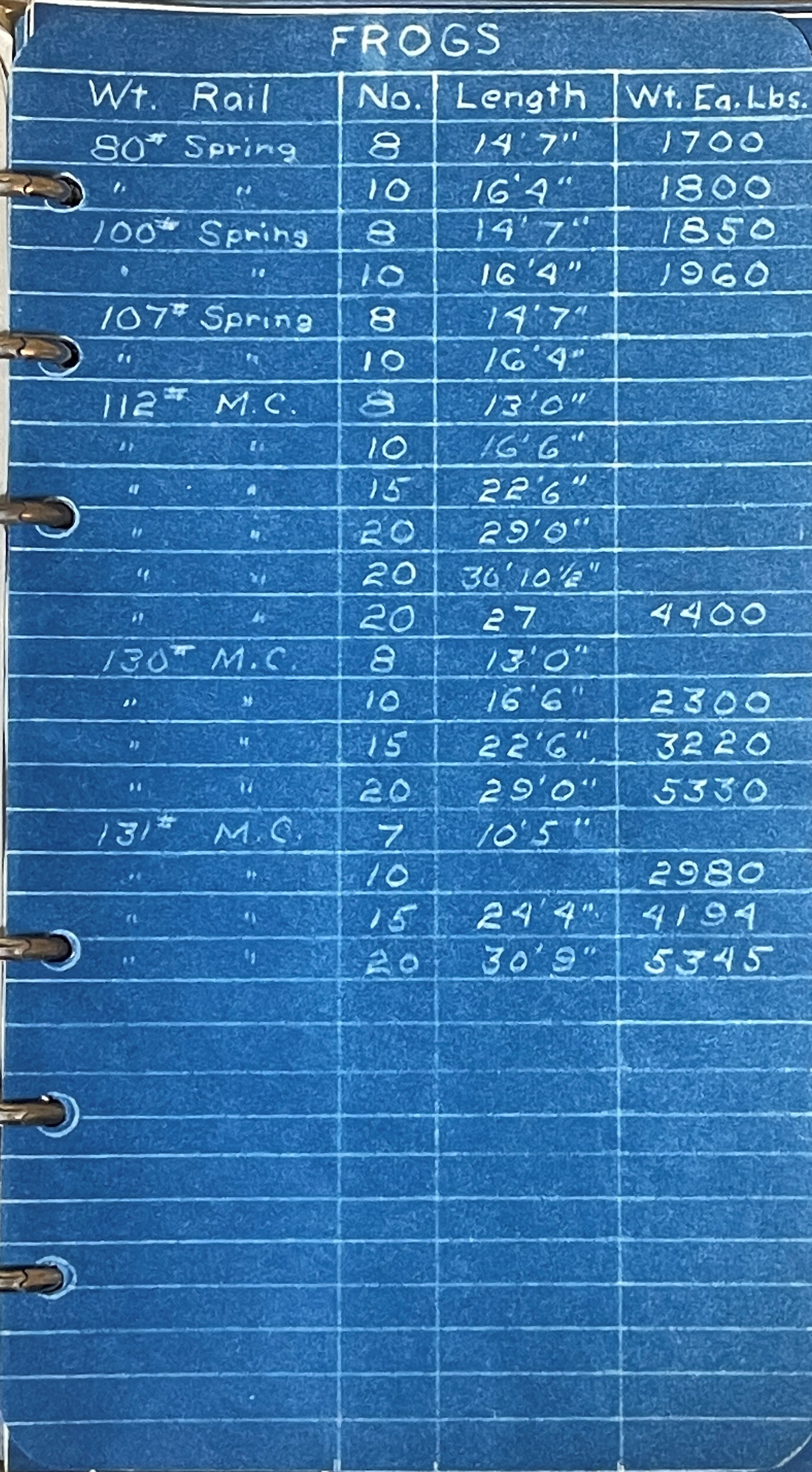
Looking at the frog, it's a manganese rail bound frog. I haven't researched the details, just know what it looks like.
It also conveniently tells us it was manufactured by Racor, is a No. 10 frog for 107 lb rail on the NH. I prefer a cast or model frog to filing your own since it lacks much of the detail. The Microengineering ones look very good. For handlaid I like the Proto87 Stores ones.
The information noted, 15' foot long switch points for a No. 10 switch, matches the data in the book I have. These are in the order they appear in the book.
As a last look at my post on rail codes, for the Cottage Grove Road grade crossing, 131 lb. rail was used. But there isn't a compromise joint bar to go from 78/79 to 131 lb, so a short section of 107 lb rail was used to bridge them. So this picture conveniently has 79 (code 55), 107 (code 70) and 131 (code 83) rail so you can see how they differ in size.