Thursday, November 28, 2019

Crossing Shanty Part V

Happy Thanksgiving!

As promised, I'll actually finish this model. Well, except perhaps for some weathering.

Anyway, next up was the roof. I started by measuring 3 scale feet up the roof with my HO scale caliper.


This gave me a line to work with. I used paper medical tape for the roofing material, we always have a lot on hand for our daughter, Emily.


I put the tape a little above the line so there will be some overlap. I marked it along the corner with pencil, then cut along those lines. I left it long so I could trim it after it was attached to the roof. I used Aleene's full strength so I wouldn't have to rely only on the stick of the tape.


I used the same basic process for the peak of the roof.


I then measured out strips for covering the corners.


I painted the roof with a spray can of Rustoleum Flat Black Primer, and hand painted the stack with Citadel Chainmail, which is essentially a black/silver mix.

I then made the storage box from .060" styrene, and covered it with 2"x6" boards and painted with the same Tamiya Dark Earth as the tower. I actually made it too tall, so I used another Dick Otto technique and sanded off 6" with 60-grit sandpaper.


Crossing Shanty Part IV

So one of the things I'm notorious for is not finishing projects. At least in a timely manner. The process of building the shanty so far has taken me two days to the end of Part III. These posts are also written well ahead of the time they are scheduled to be posted on the site, since I can write a bunch of posts at one time.

My intention was to complete this model fully, painted and weathered. When I finished the Part III process, I needed some supplies. When picking up the strip styrene, I tripped in the dark parking lot, and thought I had broken my leg/ankle. It turned out to be a very bad sprain. Since stairs are tough, I wrote out these posts the next day, which aren't being published on the blog for a few weeks. Thus giving me time to finish the build process and finish Part IV. So here we go!

The techniques for the rest of the build are basically the same.


The railings are made from 2"x4" strip styrene. In the pictures, the only support I can make out is the one diagonal brace. I may add a second to the other side, but I can't see any legs.

The windows themselves are a mix of 1"x3" and 1"x2" pieces. I started with the bottom of each window, then the top, sides, and finally the mullions.

The side window is open, as in the picture. I haven't added the top of the lower windows yet, because I need to add clear styrene to the upper window first, after painting everything.


The front window looks like it is three separate windows, and I couldn't tell if they could open or were fixed, so I opted for fixed. I created the posts by using three strips of 1"x3" with the center one sticking out slightly. Once those were in place, I built the frame of the window itself in the same way as the others, so those center posts end up as 5 layers of 1"x3" with the center protruding the furthest. On either side, each successive piece is back just a little bit more to give it the proper "stepped" appearance.

The horizontal mullions are glued to the edge of the actual window frame. I did the outer mullions first, so I could line them up with the clapboard siding, then the center ones, to keep them as level as I could.


I started the door with a square of .010" styrene for the lower part, and used 1"x6" strips for the raised portions. The top was created using the same approach as the other windows, using 1"x3" strips.

I painted the entire exterior with Tamiya AS-22 Dark Earth in a rattle can. The only color photo I have is a frame of a Kent Cochrane video, but it looks like it's just some shade of dark brown, including the trim. It's possible that it's a bit of a gold color with darker brown trim, but I can alter that with weathering if I choose. The same applies to the weathered platform and stairs.


The interior is painted by hand using Vallejo 70.644 Sand Primer from their Mecha line. I have no idea what the color should be, nor what sort of interior I'll eventually add.

Once painted, I added window glazing. The only tricky part was the open window. The upper glazing had to fit perfectly within the window frame. Then I added the painted 1"x3" for the top frame of the lower window, and the glazing behind that. The glazing is glued into place by Aleene's as usual. I'm out of Canopy Glue, but best I can tell that's a thinned PVA glue in that it dries clear and remains somewhat flexible. In any event, the Aleene's works just fine.


Next post, final touches...

Tuesday, November 26, 2019

Crossing Shanty Part III

After building the basic model, I was looking more closely at the photos, and decided I didn't like the placement of the door on the back. My initial concern what that if I moved it to the right, there wouldn't be enough space for the stairs, but after testing another position, I think it will work.

It appears the door is centered on the back, and based on the pictures, it needs to be there because the stove is in that back corner. So I ripped off the back and made a new one.


You can see that I added some corner braces in the bottom when first assembling it, and then I also decided I needed a floor since the windows are so large.


The new back wall, before straightening out the right side of the door (below the window) with a file.

I then started framing the windows and doors. I used a piece of 1"x6" for the window sill (trimming the back flush with the inside wall once dry), 1"x3" for the sides and tops of each window, and 1"x2" for the trim around the outside.


There's a piece of 1"x2" under the window sill as well. I also framed the small door, then used a piece of scribed styrene for the door itself, plus a piece of 1"x2" for the crosspiece. The stack is a Utah Pacific part. I filed off the small nubs on either side for guy wires as they aren't needed here.


To build up the right side of the door frame I built a sandwich of 1"x3" pieces, and then started on building the platform from 3"x8" (because it's what I had on hand), and 1"x6" decking.


I test fit some Central Valley Model Works steps, but they looked pretty chunky. More importantly, they are a 45 degree angle, and stuck out too far. I originally thought they would be better because they look like wood stairs that are built with the treads on top of the riser. But I double checked the picture of the stairs, and found they are inside the risers, like the Tichy ones, which are 2 scale feet wide and a steeper grade and looks like a better match.


I also noted that the railings only have a support at the bottom and the top, and it looks like 2"x4" construction. Another detail I'll try to include is the small board at the bottom under the first riser, to avoid stepping down into mud (I'm assuming). Incidentally, this picture is also why I moved the turnout to the Union Manufacturing side track from the other side of the tower to this location on the mainline.

Thursday, November 21, 2019

Crossing Shanty Part II

In the first post, I outlined how I determined the dimensions to build the two story crossing shanty at Elm Street.

Once I had the parts, and I had beveled the edges, I used a Right Clamp to assemble the basic tower.


I paid close attention to the belt rails and the clapboard siding in lining this up, since I could easily file the top and/or bottom of the tower if needed.

Using scale 1"x2" strip styrene, I started adding the belt rail and the corner trim,


I did the belt rail first, because that looked like it was done that way on the prototype, and then the corner trim. I use a piece longer than needed, glue it in place, then cut off the "handle."


I also test fit the stairs, gluing it on with Aleene's Tacky Glue, and I can easily remove it. I then tested the size on the layout, and it looks good.


Next I started the roof. Instead of looking up the math online, I started by drawing out the footprint on a piece of cardstock, allowing for a 1-scale-foot overhang. I then measured up a 2 scale foot line up past the center point, and cut out triangles to that point.


I thought those triangles looked like they would be too tall, so cut out a set of shorter triangles (about 1-scale-foot shorter). I used Aleene's again to glue them together and test.


I thought this looked too flat, so I split the difference between the short and tall triangles, and cut the final pieces out of .010" styrene.


I also added a square piece from .030" styrene on the inside that sits just inside the walls, to strengthen it and keep it centered on the model.


Next up, adding details.

Tuesday, November 19, 2019

Crossing Shanty

A while ago, Dick helped me size up the crossing shanty at Elm Street. I only have a few pictures, none of which are great. Most of the shots were in the distance.

For a long time, the only picture I had was of a fan trip with Steam Locomotive #97 in 1966:


But in a series of photos recording the installation of a new at-grade crossing on Elm Street in 1955, there was this picture:


And a second photo that catches just the stairs on the other side:


I also found a photo from an old postcard:


And Bob Belletzkie found this photo from an old newspaper article:


This final one was what provided a starting point. Where I might have used the first photo to count courses of  clapboard siding, he started with something with a "known size." The bicycle wheel.


Using the measurements he suggested as potential, I created a paper mockup.


The windows were sized based on some Tichy windows (although I don't recall which ones). I also built a second, larger one for comparison.


One concern is that it wasn't going to fit in the location where it belongs, and would have to move to a wider space. So I redid the windows on the smaller one, and while it seemed small, it also matched the basic dimensions Dick had come up with. Better yet, it fits where it is supposed to. So that's the dimensions I'll work with, about 8 1/2' square, which makes it about 8' square inside, and about 16' tall at the top of the sides. That general dimension, except for the height, seems to be about right for the single story shanties too, and I'll need at least two of those, maybe as many as five. I know there were double story ones on the Berlin Line in places too, so I might need to make at least one more of these.

Here are the two side by side:


In this context, the small one looks small, perhaps comically so. But as I continued the project I found that Dick's assessment was right on in terms of the measurements, and it means that it fits the layout.

When I was picking up some styrene at Roger's, I noticed he had clapboard siding and decided it was time to start the tower. Besides, I wanted to try some techniques I learned at Ryan Mendell's excellent and informative clinic on machinist's tools

 To start, I  used calipers to take the width of the paper mockup, and scribe the line on the siding.


Then I used a scribing tool to cut the styrene. It cuts a 'V' shaped groove, although it can be straight on the side you drag along a ruler. But it is much faster than using a knife or scalpel.


I used the pieces I cut against a straight edge (in this case the thick part of a square) to ensure that they were dimensionally the same:


Using calipers again, a took the measurements off of my mockup to transfer them to the styrene parts.


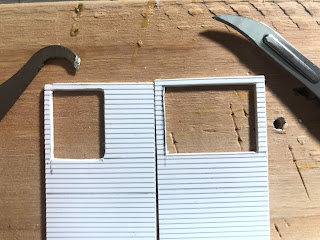
To cut out the windows I first tried the scriber, which worked well enough, but needed the corners to be squared using a file. So I tried using a scalpel with a #12 curved blade, which works much like the scriber, but is very thin. I find it works much better than a standard straight blade, and it also makes it relatively easy to get square corners when cutting out windows. I wouldn't want to do it for the 200 or so windows in the Landers, Frary and Clark factory, but it works well here.


I also decided to bevel the back edges so I could make tight corners. This shows how accurately the windows on the two sides match up when using the calipers. One was cut with the scriber, and once with the scalpel. I also used the calipers frequently to check various dimensions while sizing the holes.


In another clinic, Rich Ramiarz reminded me that you can determine measurements on a picture at an angle by subdividing with an "X." It can also be used to subdivide evenly.

In the picture with the small door (which I don't know what it's for), it looks like it's in the center of the side. I also did count the courses of clapboard to set the location for the belt rails and check the height of the windows. Amazingly, it's the same number of courses.

So I drew an "X" in that panel to determine the center. I then subdivided each of those squares using the same technique. That provided a number of precise points, and I chose the two that looked the right width. The first lines looked like it was too wide, so the inner set of verticals is what set the width of the door.


I also decided that it looked like the right edge of that lower door in that picture was in line with the right side of the windows above it. So I enlarged the windows on both sides (the picture above is before I enlarged it). Then I was ready to start assembling the tower, which I'll cover in the next post.