Showing posts with label Kitbashing. Show all posts

Wednesday, April 6, 2022

More NH 600-series coaches

 I decided I could probably improve the car I had done a while ago that looked like this:


Part of the reason I decided to do it is the piece came out when I was removing the window glass (since I'll eventually have to paint these). The I had damaged the upper drip rail and the key joint that needed work is the one on the left, next to the other window. I concluded the best solution was to square up the left side and remove the drip rail entirely since I can replace it with strip styrene.


I test fit while working to ensure that my filing work was sufficiently square.


The new windows should be flush with the back of the side, but there are mounting pins at either end (I had already "removed" the ones in the middle). So I used a piece of Masonite between the pins as a workspace and glued the windows along the bottom and left side. As I applied the liquid styrene cement I pressed the windows toward the left to make that joint as invisible as possible.


Next was to replace the missing drip rail. A piece of .030" material fit, but was too tall for the drip rail.

I tried a scale 2" x 6" for the drip rail and 1" x "4 for a filler piece, but it was still a little tall.


So I split the difference with .015" x .060" for the drip rail and .015" x .040" for the filler. It's important to have a good supply of strip styrene for projects like this. I make a point of always purchasing something when I go to a hobby store, and styrene is always a good choice if they don't have anything else I need.


Here it is glued in place.


All that was left was to fill the small space to the right. I had filed this square as well so it would easily take strip styrene. As it turned out it was a bit wider than .030" and narrower than .040". While I could have filed that a little thinner, I went with a piece of .020" and .015" and that made a nice, tight fit.


Looks much better, and didn't take me very long at all.

Wednesday, March 30, 2022

NH 600-series Coaches

Some research for various projects and continuing to clean up the basement brought an old project to the bench. This is one of those projects where each time I've come back to it I have improved my skills to a point where additional progress is possible.


This photo shows a car side I modified the last time I worked on this. It wasn't the first, but the first mostly successful attempt.

Some time ago I started acquiring Walthers parlor cars and attempted to cut the relevant windows out of one side so they could be rearranged to the correct order on another to create a 600-series coach that had been converted from a parlor car. I also tried NERS parts (designed for just this type of project with Rivarossi passenger cars) and Branchline (now Atlas) parts. 

At the time, I tried to carefully cut out the windows. While the styrene is soft, it's still a chore. More importantly, the cutting kerf, makes it very difficult to do in that manner.

Here's another earlier attempt (top) with its uneven cuts, a few gouges, and Branchline windows next to a Walthers window. 

Of course, when I looked at the project now, I have no intention of using the donor side for anything but parts. As you can see from the B&O side, I've cut well around the portion I'll need, and I can file it to the proper size for a much better fit.


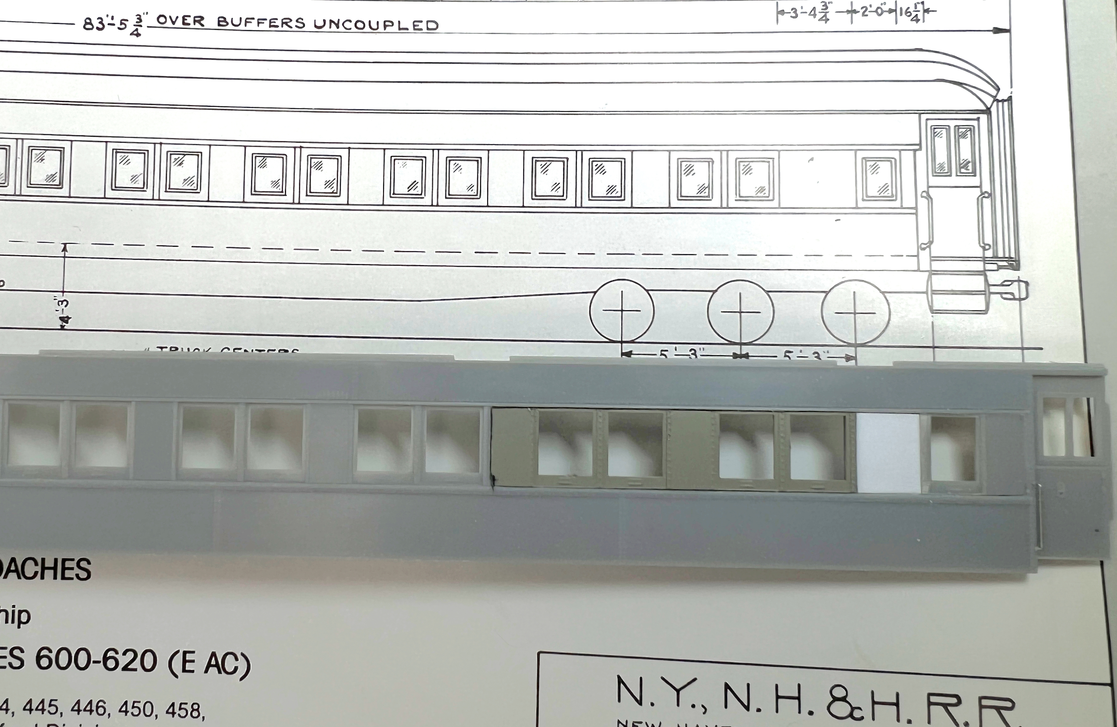
As you can see, I'm using the New Haven sketch published in an excellent article by Wayne Drummond in Shoreliner 21.3. Assignments of the first 20 cars to be converted included the Highland Line, and eight of them were of this design. I need two additional pairs of windows from this car side.


I haven't finished filing them here yet, but this is the location where they will be.


When cutting out the windows from the side I'll be using, I make sure I'm well clear of the details I want to keep, and will file to fit again.


I repeated the process for the small window at the end and used .040" styrene to fill the space between them. Although I measured the distance from the end for the small window, I should have spaced it the same as the other end. It looks too far from the end. I'll probably do one more of this plan and will adjust for the second one.


Here it is mocked up on the car side, this time it only took an evening to make. The roof doesn't fit properly yet since it needs to be reversed.

Seen below it's next to the earlier attempt (that used one of the other plans). I'll have some cleanup work on that one to fill the gaps, but I think it will work OK. 


Of course, the other side of these cars is the same as the Walthers kit as is. On my layout you can only see one side of the cars, so I could have just gone the easy route. But I'd prefer to run these sides as the visible ones, since I find their heritage interesting and they are cars unique to the New Haven.

It also turns out that they will be more important cars than I originally thought. While the consist books show the 8270-series 11-window Osgood Bradley lightweight cars in addition to these heavyweights, almost every photo or video I have of passenger trains on the Highland have heavyweight cars. These were replacements for the older cars that I'll also be modeling. These would have run from 1949 until the trains were replaced with RDCs in 1952-3.

Friday, May 28, 2021

Improving Intermountain AAR 70-ton Flat Cars

I started this post in June of 2019...Yep. Another flat car project.

The Intermountain AAR 70-ton flat cars are really well done models of an important prototype (including a New Haven one), and I have several of them. The only issue I have with them is that the laser-cut wood decking is a bit too thick, and tends to delaminate and curl. One option is to thin out the deck and glue it better. But I also wanted to experiment with doing a board by board deck, which should be a simple enough project with this model.

Despite the decking curling at the ends, it takes a bit of work to remove. It's installed using double-sided tape. I peeled them off, then scraped off any tape that was left.

I didn't have any 2" x 6" styrene strips at the time, so I started with the wood strips I had handy. I used my always on-hand Aileen's Tacky Glue to glue them in place. 


This process was working OK, but I have found that I really prefer working with styrene. In addition, the laser cut deck has boards of several different widths. I tried to find some prototype diagrams or information that would verify this, but I haven't been able to do so. So I decided to go with Intermountain's research and replicate that.

I built a simple jig to help keep things aligned using a couple of pieces of Masonite glued to a Masonite base. I have some passenger cars to scratchbuild/kitbash and this was built to prepare for that (coming soon!). 

I found that I needed to do a few pieces then glue them, otherwise they wouldn't stay in position for long. As you can see, I built them alongside the Intermountain deck after cutting all of the pieces using the Chopper.


I also ended up building it in two halves (unintentionally, actually, but found that it let me file to fit around the bolster and figure out what width the final piece needed to be). I also installed stakes in the stake pockets on one side, to help in alignment and trimming the stake pocket slots.


It's a good fit. 


I did finish the wood deck as well, even though I may not use it. I also made the end pieces, but I haven't cut out the curved area for the drop brake wheel or the deck stake pockets yet. I also didn't make nail holes yet. Instead, I'm going to have a friend make some castings. I'll modify the castings to make a final master to make several, since I'll need a few. If they come out well, In the meantime, I have a few more that need to have their decks removed.

Wednesday, May 19, 2021

Modifying the Tichy Flat Car Part VII

In the first post I showed how I modified the deck and assembled the basic kit.

The second post covered scratchbuilding side sills and measuring and installing stake pockets. The third post covered how I was handling the rivets with an addendum from my buddy Bill Gill here. The fourth covered some additional prototypes. Fifth was the underframe on the NH car. Sixth was the end sill and deck of the NH car.

The impetus for this particular project was a photo of a T&P flat car which also includes prototype information for that and similar cars.

Since I had the CofG kit, I decided I might as well finish that one too. The set of decals comes with a diagram for the car, and it's about a foot longer than the Tichy model. Should I bother?

Sure, why not? In this case it's just adding a single board to the length. As I was reassembling the deck, it occurred to me that instead of just cutting it in the middle and then cutting a single board from a spare deck, it would have been easier to cut out a chunk of, say, four or six boards and replace it with a piece of five or seven boards. That would have been much less fiddly than trying to square and insert a single board.

They have some photos online of when they moved the car and a work session. It is noticeable that the fishbelly center sill wasn't as deep as the Tichy model, much like the NH car. I thought that the center sill from a Branchline (now Atlas) ACF/URTX reefer would do the trick. It's about the correct length after I added the extra board to the middle:

This is too deep, here it is compared to a spare bolster:

It looked like I could cut along the rivet batten at the bottom and it would be just right.


Then it was a matter of filing the slots for the bolsters deeper to accommodate the change. I also trimmed the tab off of the bottom of the crossbearers (that fit into a slot in the Branchline underframe):


Then I remembered that the center sill sits below the level of the crossbearers which sit on top of the stringers (when assembling the model). So those tabs probably could have stayed.


I used some strip styrene as a spacer while assembling it. When looking at the photos of the work session, it's apparent that there are two stringers between the crossbearers, so I filed slots to allow that placement:


The crossbearers and stringers are a little short, but not visible when the car is on the track, so I decided not to worry about it. For the other stringers, I just used scale 4"x4" instead of building channels:


The end sill is a channel facing outwards, but deeper than the one on the Tichy model. So I fabricated a new one from styrene:


After applying that, I cut out the coupler pocket:


The shallower center sill is quite evident next to the unmodified Tichy kit:


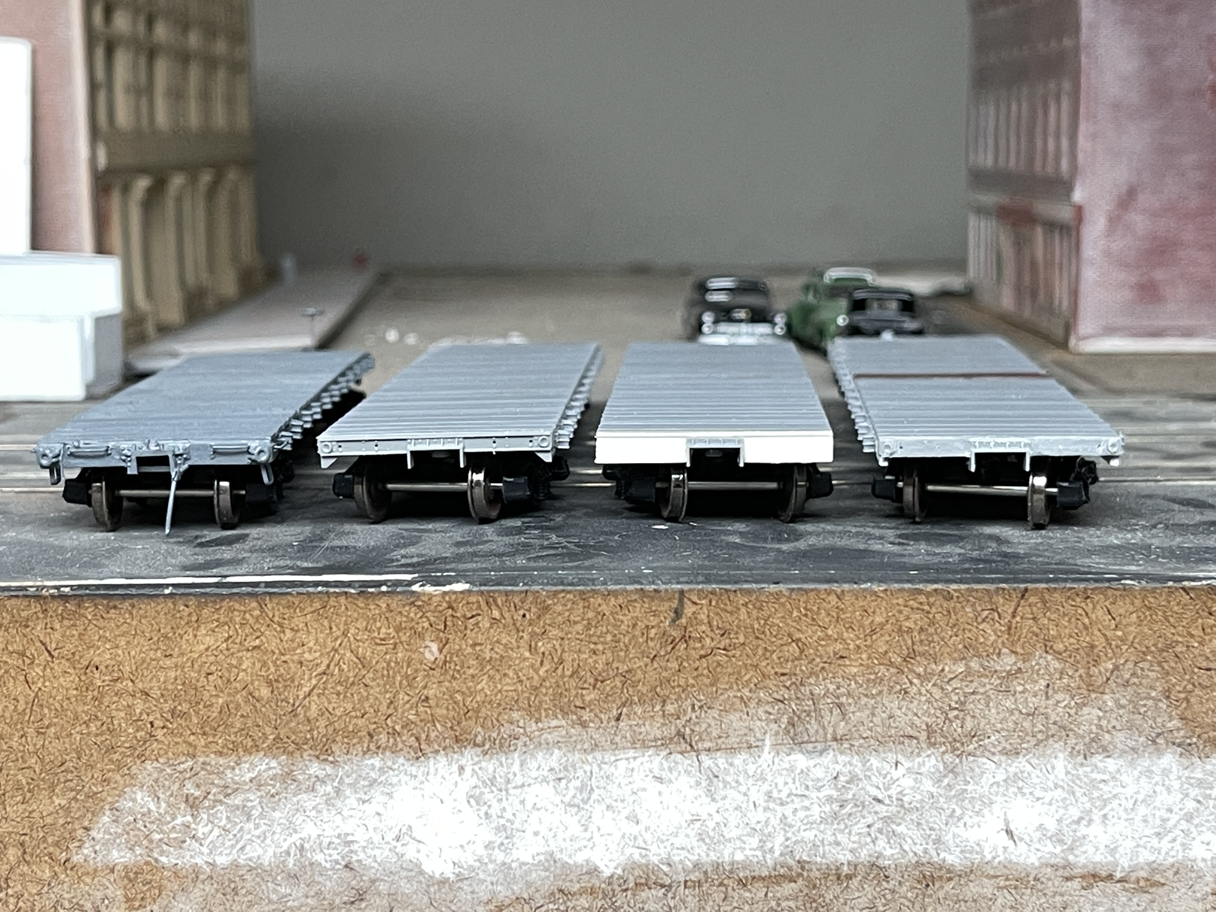
Four different ends. The NH on the left, the NC&StL (unmodified Tichy) next, the CofG one (with details to be added), and then the T&P one which is the Tichy end but with the channel flanges removed.

Note that I used the Tichy striker casting for the CofG end. It's not a perfect match to the prototype, but was a simpler solution than scratch building it.


I didn't have a good shot of the side to figure out the stake pocket spacing. But I also don't see many extra rivets in the photos. It occurred to me as I was experimenting with spacing that if one side of the stake pocket lines up with the crossbearer or stringer, then the rivets for the underframe components may have also been used to attach the stake pockets. So I used the underframe as a guide for the spacing. Since it seemed like all of them had similar spacing for the first two stake pockets from either end, I retained that spacing, then spaced the rest according to the underframe.


I still have rivets, grab irons, and other details to add, and I'll be doing the rest of those features on the other flats too. I really like the way this one is coming out. More to come.


Friday, April 23, 2021

Modifying the Tichy Flat Car Part VI

In the first post I showed how I modified the deck and assembled the basic kit.

The second post covered scratchbuilding side sills and measuring and installing stake pockets. The third post covered how I was handling the rivets with an addendum from my buddy Bill Gill here. The fourth covered some additional prototypes. Fifth was the underframe on the NH car. 

The impetus for this particular project was a photo of a T&P flat car which also includes prototype information for that and similar cars.

With the underframe done, I needed to work on the body of the car itself. The side sills were done the same way as the other models, with strip styrene, the Tichy stake pockets, and harvested rivets. The car at the Trolley museum has some extra holes drilled on the side and end, but I skipped these as they looked to have been from various repairs over the years. 

But the end sill was quite different from the kit.

End Sills


B-end


A-end


I couldn't get a good full shot of the ends since it is sitting between two other cars. The end sill itself is just a simple steel channel with the flanges turned in toward the interior. In other words, from the outside it's just a flat end, and very easy to model. But what intrigued me was the rather substantial buffer, and the cast poling pockets that wrap around the corner. Also note the B-end is missing the handbrake altogether, although the support under the sill and retainer valve are still present.

Poling Pockets

I've been looking into the possibility of getting these 3D printed, but the parts are so small it may not be possible. A second option would be to 3D print the entire end sill. But I decided since I was working on these cars now I'd see if I could scratch-build them.


The casting is attached with two rivets on the end, and two on the side, one of which also attaches the grab iron. It is angled slightly toward the side, and has two stiffening ridges. The deck is entirely gone, so you can see how the end sill channel is notched to fit into the side sill (which is also a channel), and how the poling pocket casting ties it together.

I decided to try to replicate this, using a Cal Scale poling pocket and building the casting around it.

Because I find it easier to build something up, than to cut and shape it, the end sill is made of of three pieces of strip styrene. One across the top of the coupler pocket, and one on either side. Using liquid styrene cement means it will behave like a single piece when attached, and I brushed the cement across the face of it then smoothed it with a fine finishing stick to hide the seams.

After marking the end the width of the poling pocket casting, I glued a length of strip styrene to the end.


I found the easiest way to do this was to hold it on the end, and apply the liquid cement to the inside corner on the side. Once that tacked it down I could remove my finger and glue around the other sides of the piece. If you accidentally apply too much, don't touch the piece until it dries. The cement melts the plastic, but if you don't disturb it or squish it, it will be OK.


I then bent it around the corner, marked, cut, and glued it to form the corner casting itself. Next I drilled a hole for the poling pocket casting, at an angle since it would need to be tilted toward the side of the car:

These are the tungsten drill bits I got from Amazon, and I've found that the shaft is large enough I can just use it by hand for this. I then used a reamer to widen the hole.


I glued the poling pocket at an angle, then formed the casting with some thin strip styrene.

After doing the first two, I found gluing the center first, then bending around it once that had set worked best.


This is a process of bend and glue, bend and glue, and then trim once it has reached the desired shape. I then glued two pieces to form the stiffening flanges:


As you can see, I leave a good sized 'handle' to work with, then trim it once it has set.


It's hard to see with everything being white styrene, but I'm quite happy with how they came out.

Uncoupling Lever

The uncoupling lever is just bent wire, but after gluing it to the top of the end sill, I used the same approach to glue and bend the brackets.


Buffer

This is a fairly substantial casting, but built the same way. I used several strips to make the basic shape, then glued on the flanges, applied rivets, and finally the face.

Shaping the mounting plate.


The 'box' is built around the coupler opening, now I'm making the first two stiffening flanges on top.


Once those have dried and are trimmed, I installed the rivets, then added the center two flanges.


One of the side flanges is trimmed, the other is about to be.


Test fitting (and testing with) a coupler.

When looking at a complex shape like this, it's good to identify the individual parts that can be used to fabricate it:


The way I broke this down was the back part. The first one I did I made the curved part of the plate that attaches it to the car, but it's so small I didn't bother on the second ones. I did narrow the coupler pocket significantly and have found this does not affect operation.

So the back plate was a piece of styrene across the top, plus one on each side. I then clipped diagonal and vertical to step it in toward the coupler.

The next step was to form the box around the coupler along the edge of the coupler opening.'

The stiffening flanges are more styrene, long then cut to shape. Four on the top, then one to each side, plus the one a the bottom. Add the rivets, and then add the face. Again, I did this as a piece across the top, then trimmed an angle for the side pieces before gluing them on.

It's fiddly, but once you are able to visualize it as individual parts, not too difficult to build.

Unfortunately, either my primer or glue application was too heavy, because once primed most of the rivets aren't as noticeable.


But overall I'm very happy with my first attempt at this sort of detail, and being an old car some weathering, dirt, and rust will help make the buffer look correct anyway. I may be able to bring out the rivets a bit more in the process.

Deck
As I mentioned, I decided to make this a very well used car by heavily distressing the deck. I simply carved it up with a scalpel, and used a brass wire brush to clean out the grooves. It was fun digging some real gouges, and I also have two holes going all the way through the deck. I had to carve and try to thin the edge of these holes from the bottom, because the deck is fairly thick in the main body.


It will need a final coat of black paint for the car body, and an unpainted (and well weathered) deck. I also have to see what decals I can dig up, and also if I can find an photo with its in-service lettering instead of the MoW lettering.