Thursday, August 27, 2020

Modeling NY/YN Freights - DERS-2b (RS-2) 0502 and 0503 - Part VI

  Part IIIIIIIV and V...

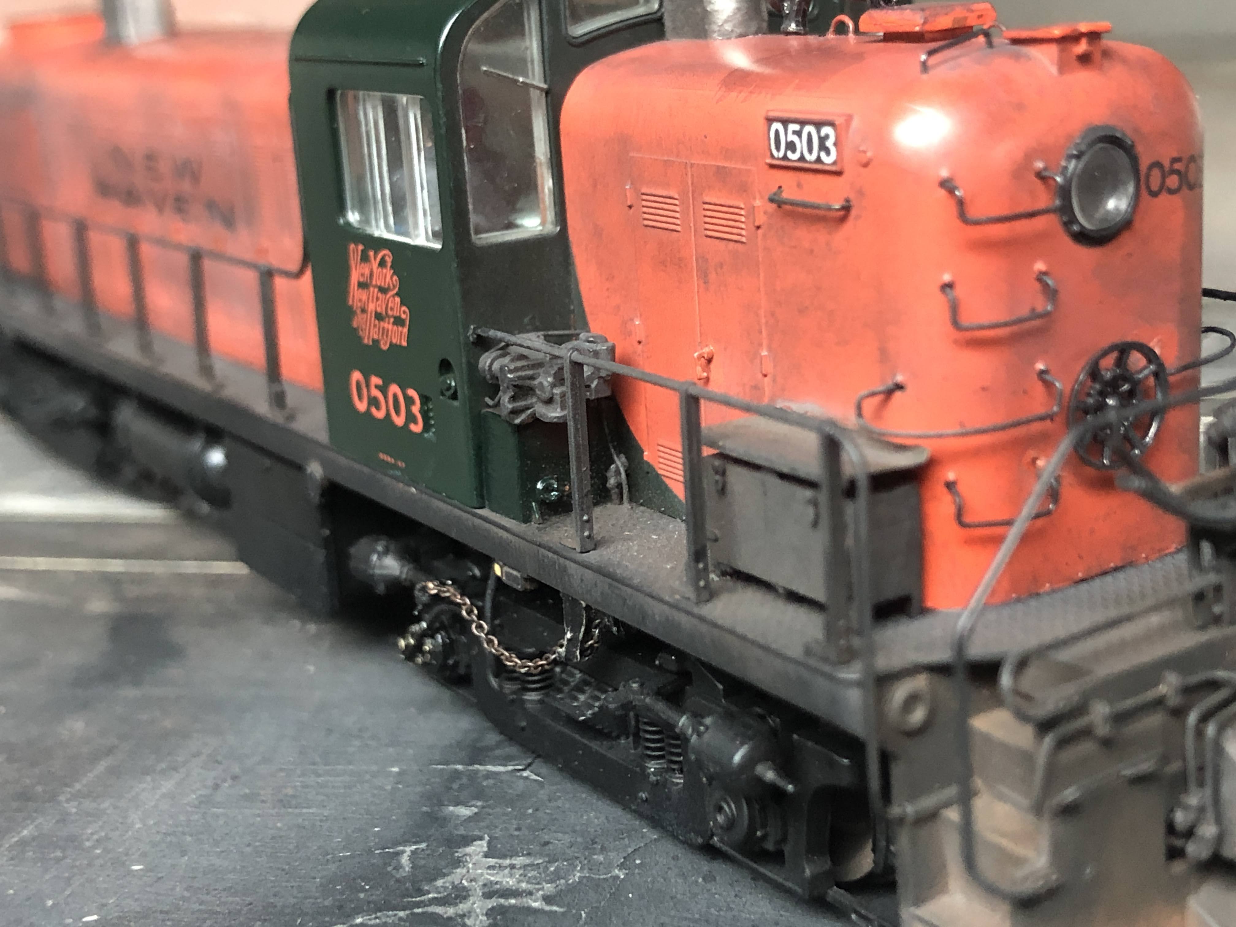
I know I said this was going to be a short couple of posts, but as I've been looking closer at photos, I keep noticing some other details I want to try to include. Case in point, when examining this photo of 0502 and 0503 in Plainville c1948 (photo by Cochrane)...

...I noticed something on the walkway that I hadn't seen before. 

I don't know what that little thing is just behind the railing stanchion, but there's one at the other end too:

Looking more closely at this photo of 0509 (photographer unknown), it's there as well:

We can see it more clearly. Examining other photos, they appear to only be on the engineer's side. In part because I want to get better at scratchbuilding, I wanted to see if I could make these. It's another example of something that I have no idea what it is, but all I really need to know is that it is there, and what it looks like.

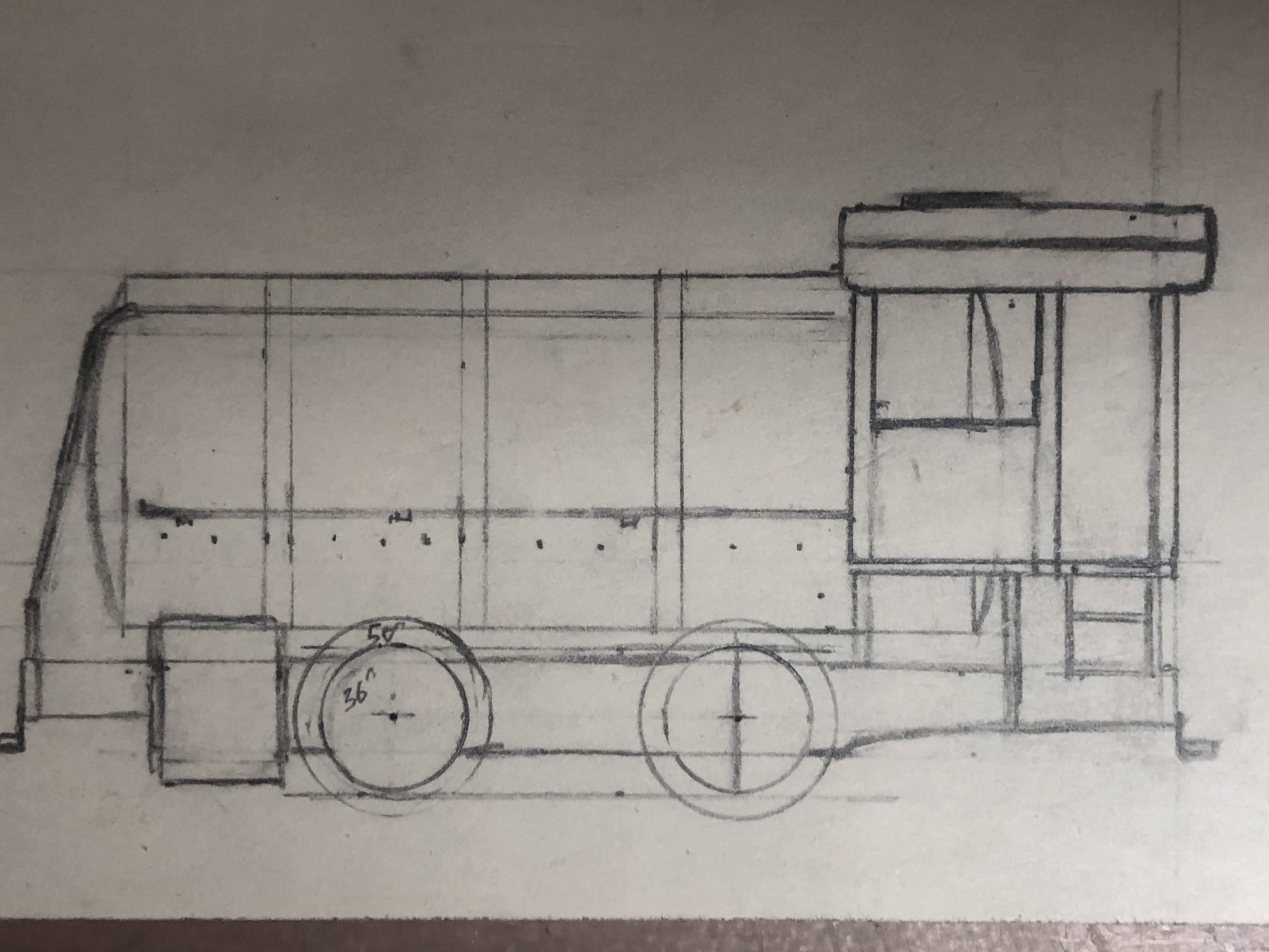
So I started by drilling into the end of 0.020" styrene rod, and inserting a short piece of 0.010" wire (I think, it was scrap).

After cutting the styrene to a length that looked good, I sliced a thin sliver of 0.030" styrene rod to make the cap:

Then it was a simple matter of drilling a hole in the walkway and installing it:

One tip - really good drill bits. I recently ordered some from Amazon for a slightly different reason. One of the challenges I often struggle with is getting a wire-gauge drill bit chucked up so it is straight. The slightest bit of off-axis alignment means the tip is moving quite a bit out of alignment, often causing it to walk, or break. I thought this design would make it much easier, and it did, since it's a much larger portion to chuck. In fact, it's not much smaller than the maximum my Dremel chuck will accept.

So as I thought, that worked great. What I didn't expect was how sharp they were. The first thing I needed to drill was a hole in the metal frame. It was like drilling styrene it was so easy and fast. They are incredible. I've even used them as their own without the dremel or pin vise, as the 'handle' is large enough as it is. They do break easily with any side-to-side force, but I've broken far fewer since they drill so well. I highly recommend them. They do come in many different sizes, all labeled in mm, so you can consult a chart like this to select the sizes you want. 

BARCO Steam Lines

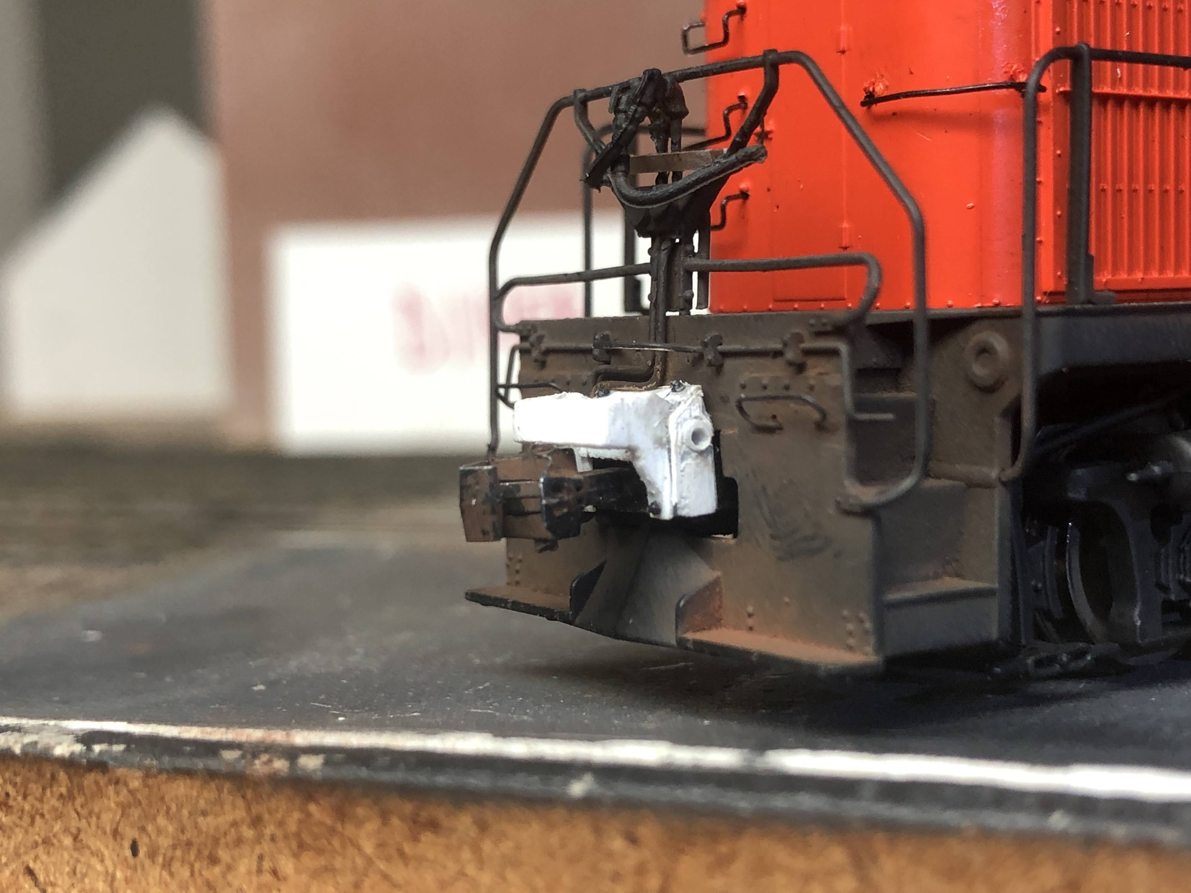
I also cut out the front of the pilot to allow installing the BARCO steam lines as seen in the picture of 0502 and 0503 above. To do this, I notch with the corner/edge of a file to define the width, then continue to shape it with a file.

I used Custom Finishing parts. They are cast in a soft pewter and aren't quite as crisp as the brass ones were. These are spun cast in rubber molds, and it's also clear that the molds are old because many of the parts are incomplete. You can see the difference between these two castings:

In the first one, several of the parts are malformed, including one of the BARCO steam lines, which are the only parts I'm using from this casting. So I recommend ordering at least one extra set of parts. I usually do this anyway, since there's a good chance I'll lose or break a part anyway. If you can find the brass version, grab them. I'm happy that they are still available at all, and an occasionally bad casting is not something I worry about.

After bending the casting so I could glue it against the inside of the pilot, I used 0.010" scrap styrene to put across the bottom to complete it. I did a quick paint/preliminary weathering as well.


Hand Brake Chain Guides

Stephen Wintner asked how I installed the truck chains. I started by drilling the holes for the two parts of the chain guide. The Custom Finishing set has a third part, with the wheel horizontal, but they aren't used on the NH locomotives.

Incidentally, I also ordered some of the new Cal Scale plastic ones, which are the two parts with a plastic chain between them. Presumably you can add a real chain to the truck, but I didn't care for the appearance, and it would also have required drilling two holes in the precise location for the parts to install properly. Something I'm not good at.

Although I originally used a No. 70 or 72 bit (I think), I used the new 70 mm one for the final hole. I then filed the pins, especially where it meets the part, so it would fit properly against the bottom of the chassis. It also requires reaming out the hole for the larger chain guide so the 40-lpi chain will fit through it. 

I install only the smaller guide (the small wheel) first. I then make a small needle by bending 0.006" wire. Rather than bending it against the edge of the needle holders, I use them to hold the wire and bend it free-form to make it as small a hook as possible.


I thread it through the end link of the chain from the straight end (not the hook) because I find that easier. Then I crimp the end. I have two needle-holders for this. Holding the wire with the needle-holders locked in place prevents the wire from rotating when crimping the hook with the other one.


It's much easier to thread the chain through the guide using the 'needle' that we just created. Make sure the chain guide is facing the right direction. I then thread it through the smaller guide that's attached to the model already, then bend the wire around the back and glue the wire to the bottom of the chassis with ACC.


That keeps it secure at that end, and also prevents the chain from filling with ACC and stiffening. I then drape what looks like a decent amount of droop for the chain, and cut to length.


I then make a new 'needle' for the end of the chain.


I thread that through a hole I drilled in the end of the brake lever, and bend over the top and bottom, then glue the needle in place. This photo shows it bent into place, but before snipping of the excess wire.


This is an evolution of the process I used on the one RS-1 I've done so far. When I did the first RS-2, I hadn't installed the LEDs yet, and the way the chassis is designed it could be set upside down and worked on that way. For the second one, I had already installed the LEDs, so I used the foam cradle. This ended up being an advantage, because one of the things I struggled with the first time is the weight of the chain itself constantly pulling the chain out of the holes when I was trying to thread them. With the foam cradle, I could lie the chain on the foam slightly above the truck I was working on and it made it much easier.

I have a couple minor details left to add to the chassis, and I'll (re) weather the walkway and chassis. The shells are basically done, and I'll put them together.

Parts Used in this post:
The model is a Life-Like Proto 1000 (now Walthers Proto) RS-2

Custom Finishing Models (order direct)

147 ALCO Handbrake Chain Guide
336 BARCO Steam Heat/Trainline Hoses

 Detail Associates (find on eBay)

2210 Safety Chain - Black, 40 links/inch 

Tuesday, August 25, 2020

What else am I working on? Fast Clocks

I will need a fast clock system, and I knew I didn't want a digital one. In addition, since I have an MRC Prodigy system, there isn't a fast clock that ties directly to it like NCE or some others, as that wasn't a feature I cared about having in the DCC system itself.

Instead, I'm using Mike Dodd's analog fast clock system. You can get the controller and movements as kits or pre-built by Mike.

Although I prefer to not have anything sticking out of the fascia, I don't really have any open walls to put the clocks. So I ordered some smaller clocks from Klockit to build into the fascia itself.


Once I build the control panel, I'll install the hands and start testing. I have 4 of the smaller ones to place around the layout, and as many as 4 larger wall clocks that I may be able to find a place for. I want to make sure they are visible for the crews and the Agent.

Thursday, August 20, 2020

Modeling NY/YN Freights - DERS-2b (RS-2) 0502 and 0503 - Part V

 Part IIIIII and IV...

Chris and I had a chance to see what other photos we could dig up. So here's a collection of some detail photos for the project.

One thing I find interesting is that I've located a number of photos of NY-2/YN-3 with J-1 and DEY-5 (S-2) locomotives, but not the DERS-2b (RS-2) engines that handled these two freights from '48 to '52.  

Well, that's not entirely true. We have a photo of Tom Davenport in 0503 on the 'Canal Local' in 1948:

However, I now believe this photo is of the southern Canal local (New Haven to Plainville via Cheshire) since it was handled by 0503 in April 1948, and was identified as "Canal Local" in the NH records, rather than YN-3/NY-4).

We also found 0502 and 0503 in Plainville in an undated Cochrane photo, probably c'48/9:

On a busy day it wouldn't be surprising that two would be needed. If you recall from the Arranged Freight timetables, the tonnage rating for the DERS-2b on NY-2 is 1500 tons from Meriden to New Britain due to the 1% grade on the Berlin Line. Coming back from Westfield it's 1700 tons. Assuming an average of 50 tons per car in this era, that's a 30 to 34 car train with a single engine. But based on the assignments I'll generally run them with a single locomotive (although I'm hoping to extend the 'Cedar Hill' staging track to allow a 30-car train).

This shot does give us a great look at the pilot of 0503 that I wish I had a few weeks ago...

Note how there is an opening for the BARCO steam lines, and how that part of the pilot is slightly lower than the footboards. That's actually a good thing, because I'll cut out that opening to add the steam lines, and I won't have to worry about keeping the bottom portion since I'll add that with strip styrene.

If you look closely, you can also see a second angle cock on the right side, above the air hose. In other pictures there are two air lines. I may add a second line to 0502, and just the angle cocks on 0503 for that variety.

There is also something on the walkways of both engines in front of the engineer:

There is also something in the same place on two other undated photos we found of 0509 and 0513 (photographer unknown). They are copy negatives and were extremely overexposed, but they do provide a lot of detail:


Here's a closer look at 0509:

My guess is that these are rerail frogs, and that's what I'll get for my models unless somebody else can verify that they are something else. Other small details that I haven't seen before (or seen only partially):

There's a pipe running down the back of the pilot. There's actually a globe valve at the top that I could spot in another photo. So I can add those. You can also see that the large (overflow?) pipe in front of the engineer has a right angle bend into the side of the hood. Not something I'm likely to change at this point (it's subtle), but I'll probably add the nbw castings to the right of it. There are a couple of other pipes visible that weren't evident in other photos that I'll add under the chassis.

Even though the angle is mostly from the side, we can clearly see that the pilot arrangement is different between the first (0509) and second (0513) deliveries, since it appears that these were both taken early in their life and at the same time. 


You can see the twin air pipes next to the coupler on both locomotives.

Initially I considered alternatives for the handrail stanchions, since the Proto ones have an angle bracket that is what pushes into the walkway, with the vertical portion just resting on the walkway instead of going into it. As it turns out, that's exactly how it was constructed on the prototype as well - the vertical stanchion is bolted to the angle that is bolted to the walkway. This is one of the main reasons I didn't alter the railing on the pilot, even though it's incorrect. The railings and stanchions are so fine on the Proto model that I couldn't drill holes for bent wire railings. If/when I get the Smokey Valley Model Works ones I might experiment, but it's hard to believe they will look better than the Proto railings.

Another detail - back when Chris was researching and detailing 0510, he was certain that the horn and steam generator intake were on the center line of the short hood, as opposed to the RS-3s which are slightly off-center. We searched and couldn't find any documentation or photos, however. After he completed it, I got this photo from eBay for him that shows just that:

It is particularly evident on the locomotive in the background. You can't see the steam generator intake (was it removed? The BARCO lines are also gone), but the horn is clearly centered. Photographer and date unknown (but it's the McGinnis era or later). I love the cinders and dirt along with the sand from testing the sanders.

Speaking of 0510, I've been considering completing the third one I have since it's numbered 0510 already. Why? Because it served for some period of time on 131/136:

We have several undated Cochrane photos, although this is probably the best one. It's also appearing on a shorter train, and we have 0507 on 131/136 too. The April 1949 Engine Assignments has 0510 covering this run, and it probably started in December of '48 after the last steam run. In fact, it was most likely the delivery of this locomotive that ended steam on the run. Considering the foliage I would say it's spring/summer '49.

By September it had been replaced by DER-1 (DL-109) 0707 leading one to believe it wasn't powerful enough for the 5-car run. Since it's not likely to have actually run during the periods that I modeled, we decided that Chris can just being 0510 over for a run if I decide I'd like to have it on 131/136.

Tuesday, August 18, 2020

What else am I working on? Stanley S-1

No, it's not an Alco S-1, it's the road number for their HK Porter 0-6-0F (fireless) steam locomotive.

About a month ago I had a coworker test positive for Covid-19. Since I had worked with them, I needed to get tested and it would take 4-5 days for the results. In the meantime, I had to isolate myself from the rest of the family, and since several of Emily's nurses wouldn't come in until the results were back, Laura was on Emily duty 24-hours a day for that time. I tested negative, and fortunately I didn't have to wait another 14 days to take a second test (and the 4-5 day wait after that). 

But on one of those days in isolation in the basement (it's never as much fun when you have to be down there...) and I was thinking of what sort of things I needed to do so I could get out of the house and away from the family, it occurred to me that I could take a road trip. To Watertown, NY, where the old Stanley locomotive is sitting outside after being damaged in a fire. 

So I took the 4 1/2 hour drive (starting about 1:00 pm), finding out it was near Amish country, and also the second largest wind farm in the country (Maple Ridge) with 195 turbines spread over 22,000 acres. 

It looks like the entire property is abandoned, but I knew I planned on staying away from everybody (since I had been exposed), and just taking pictures and measurements. I've been planning this for years.

I got my photos and measurements, made a quick sketch, and started reworking my mockup using a Mantua chassis.

Lots of work (and decisions to make). The tank car tank is the correct diameter, and I had used it as a mockup for years. The S-1 has ~35"ish drivers, and the Mantua is 50". But I don't have to figure out how to make the valve gear with the Mantua chassis. Also, even though I know the tank car tank matches the dimensions, it looks small, although that could be because of the size of the drivers and the current height above the frame. The cylinders are pretty close to the correct size. 

I think the feel is more important than being exactly correct, and my current plan is to work with the Mantua chassis to get a completed locomotive operational, and then work on scratchbuilding a more accurate one. 


Thursday, August 13, 2020

Modeling NY/YN Freights - DERS-2b (RS-2) 0502 and 0503 - Part IV

Part I, II and III...

Next up is an often seldom-modeled detail - coupler buffers. In the case of the DERS-2b this consists of two parts. First is the actual buffer, which is a large casting that is also a close match to what is used on the DERS-2c (RS-3) locomotives. The New Haven also had an extended buffer since these were assigned for passenger service. This is shaped steel and you can see that it is bolted to the buffer itself in the picture below:


If you examine the photo closely enough, you'll see that there is an upward angle on the top portion that mirrors the angle on the bottom. This is a piece of steel in a 'U' shape, open at the top for the uncoupling lever to attach to the coupler below. Also of note is the hole in the side of the buffer itself. I'm not sure what it's there for, but I wanted to try to capture it.


This is my first attempt, which I determined was too small altogether, and too short top to bottom. But like many of my experiments, it served as a proof-of-concept so I could go about making the four buffers I'd need, and was very helpful in figuring out just how I'd go about it.

The starting point is a standard Kadee #242 snap together gearbox (coupler box). I trimmed two pieces of scale 2" x 8" cut .185" long, then cut an angle with the front edge measurement at .125" to form the sides of the buffer.


I used .040" x .080" strips for the sides and the front of the buffer. I just eyeballed this measurement based on test fitting with the coupler. 


I glued a couple of small pieces of 1" x 3" to the front, and then small triangles of the .040" x .080".


I notched the top of the passenger buffer to match the angle formed by the side, and then back up where that side ended. I then drilled a small hole in each side, and then widened it with a bead reamer so I could fit a piece of .30" styrene rod inside the hole.


I trimmed the styrene rod and sanded it to leave it just a little proud of the side. I then drilled out the center of it, and reamed it to widen the hole. This formed the ridge around the hole. I then use some scrap styrene to make the top of the buffer itself, and glued 4 nbw castings for the attachment points of the passenger buffer. I filed the edges and corners (and the inside of the front of the buffer) to give it that slightly rounded look of formed steel.

For the other three, I used a small piece of scrap to form the front face of the buffer before attaching the front of the passenger buffer itself. It was easier than trying to do it after it was built. You can see the other completed buffer here, with the other three under construction.


The white didn't photograph all that well, but this is a test fit at this point in the process:


I was happy with that, so I finished the other three. Here are all four, and in the back you can see the (upside down) Custom Finishing part that represents the passenger buffer. 


You can see my consistency is not great, but when on the model, painted and weathered they are good enough for me.

I painted/weathered them using a Woodland Scenics Steel Rail paint pen (it really doesn't matter what color, though), and then Pan Pastels to provide the actual color. I did the same thing for the couplers themselves.


The finished buffers, along with a look at the new Cab Signal box that Jim Lincoln made for me. Jim is selling them for $10 for two, or $20 for five. I'm happy to hook you up with Jim if you'd like some.

The step above the box is Plano diamond tread material, bent to form the step, with three small strips of styrene (which you'll probably never see) as supports.


You can see I had to curve the underside of the buffer (and also file the top of the coupler) to get it to swing freely. It would work without that, but not self-center. I'm not sure I could have avoided this, since I couldn't really make the whole buffer taller. It's just a side-effect of things not being exactly to scale, but I don't think it detracts from the model.


Although hard to see in the photos, I used some of the rubber sprue from the Hi Tech Details air hose set for the air hose piping next to the coupler buffer that goes back under the walkway. I figured having some flexibility would be helpful, and I could easily bend them to glue to the back of the pilot. 

Parts Used in this post:
The model is a Life-Like Proto 1000 (now Walthers Proto) RS-2

Jim Lincoln (Contact me for ordering info)
New Haven Cab Signal Box