Showing posts with label DCC. Show all posts

Wednesday, February 2, 2022

Locomotive Maintenance

First post in February, shooting for once-a-week minimum for now.

As I mentioned in my last post, I picked up two DL-109s at Springfield. One of them had a modified roof, the other Tsunami sound. Together they give me an operating locomotive for 131/136 until I complete my models.

One of them was sold as having the "correct roof." Dale came across the model and sent me a picture, and I could tell what was done. Winterization hatches were added and then the roof repainted. For a truly accurate roof for this locomotive (0702) and era there's more to be done, and it doesn't address any work on the pilot. But for a quick fix to get a locomotive running it's great.

I've owned over a dozen of these models over the last decade. I've bought and sold them many times. They are the locomotive that pointed me to a road and era. I could easily pick up a few of the other paint schemes and do the same thing, since there are four different paint schemes that are in use during my era prior to them being rebuilt.


Here are three models. The one on the bottom is unmodified. The center is the new model with the "correct roof" which has the winterization hatches installed. The top is the shell I've been modifying. It lacks the new winterization hatches, but you can clearly see the other modifications made to the roof. It still needs two square vents that are above the engineer and fireman's doors.

All of these modifications can be made to the roof without impacting the main paint scheme of a factory decorated model. It won't matter if the green is 100% correct because the roofs got black very quickly and will be weathered accordingly.

The rest of the modifications are the pilot, and I haven't figured out the best way to do that just yet. One of the changes would require repainting the locomotive altogether so would be avoided. But I think I could do the other modifications easily enough and still keep the factory decoration intact. So those may happen sooner rather than later on the other ones.

For now, this one is the current model. The problem is, it's not running great. It stutters and stalls, and there is a loud buzzing of some sort near the front.

The first step, of course, was to clean the wheels thoroughly. I have the Woodland Scenics Roto Wheel Cleaner for just this purpose. I use odorless mineral spirits to wet the pads and then run at high speed in both directions, dragging it back and forth in the process to make sure they are really clean.

That didn't take care of the buzzing and all of the performance issues, so time to take a look inside.


The installation was done with a homemade speaker enclosure, which was rubbing against the drive shaft. This was creating the buzzing and may have caused some of the performance issues too.


An easy fix was to build a spacer of scale 6"x6" styerene. I also filled the open screw holes in the speaker and a few other holes in the enclosure with Aleene's Tacky Glue. I'm not sure it made any difference in the sound since noise cancellation caused by the soundwaves from the back of the speaker is complex, but it's good practice anyway to have a properly isolated enclosure.


I used a couple of pieces of Kapton tape to ensure the enclosure didn't lean into the drive shaft or gear tower and to secure the wires.

That resolved the buzzing and 99% of the performance issues too. Although this has electrical pickup on all six axles, there's a good chance that the axles and wipers could use a cleaning. I'll give it a chance to run for a little while, and take a closer look at those if I need to in the future.

One funny thing is that the locomotive is programmed without any momentum at all. It is really strange after all this time to be running a locomotive that instantly stops at 0 speed step. I'll need to reprogram that, but apparently for this older Tsunami I'll need a programming booster to do that. I haven't set it up on a programming track to see if that would work, since I don't have a dedicated programming track. 

Monday, September 20, 2021

Feeders and Exploring DCC for the I-2s

I've been working on one of my least favorite parts of the hobby - feeders. It's really not that bad, especially once I get started. I just have a lot of them to do. I've done about 15 pairs by the time I took this photo. 


Working at Whiting St. Yard.

Another 16 pair or so to go in Whiting St. Then I still have the Berlin Line, some in staging, the east side of town and the west side including Stanley Works. Yep, lots of feeders to go.

I have also made more progress on building the new website. 

In addition to making progress on what I should be doing, I also had my Crown Custom I-2s sitting at my desk, and started planning how I'll install DCC, sound and weight. I have an opportunity to get a couple that have already been weighted and upgraded to DCC. I'd have to sell mine, and hope that I cover most of the cost of picking those up.

Another potential factor is I have different goals that I'm trying to accomplish with my installations, and those wouldn't be set up the way I'd like. They would work great, of course, I'm just looking to do something a little different.


An ESU micro (or a Soundtraxx Tsunami Micro) will fit behind the motor. Both have a Next18 18-pin connector. This means I can do all of the wiring first, and the decoder is removable if I ever need to replace it. As a result, I plan on using these pretty much exclusively, even if the larger version would fit.

Chris prefers the Tsunami decoders for steam. Since he's fired real steam locomotives and understands the most minute details about operating a steam locomotive, I trust his judgement.  I checked and (as expected, due to NMRA standards) the pin-outs are the same, so by installing that wire harness, I can use either decoder.

Why not put it into the tender? Because if the decoder is in the locomotive, I only need to run two wires to the tender (for the reverse light). The power from the tender comes via the drawbar. In my era the lights weren't used during the day, so I don't even have to do that if I don't want to.


There's also space above the motor. Of course, I can't see inside it to tell, but a rough measurement tells me that there's quite a bit. As a test I put two layers of .080" styrene the length of the open section inside and the chassis installed without any issues. So there's room to add quite a bit of weight. I'll need that since these will have to haul as many as 5 passenger cars up the helix.


There are two electronic components (I removed the shrinkwrap) that go to the headlight. I haven't opened the tender to see if there's a similar one to the reverse light. One is a diode/bridge rectifier. I can't find it by searching for the markings on the internet, but I suspect they are for helping to protect the lights and maintain better continuity on DC. They won't be necessary if I replace the lights with LEDs, but I will need to fit in resistors. That won't be difficult, though, there's plenty of space.


I do, however, like the small plugs used for the lights. In this case there's one in the boiler and there's a second one in the smokebox. This allows you to remove the smokebox cover and unplug the light, and the same thing when removing the boiler from the chassis. I may very well consider similar connectors for other installations.

There's also space for the speaker in the front, here's an example of an I-2 that Tony's Trains did with the speaker in the smokebox. In this case there's also a speaker in the tender. I'll consider that, although I may try with the single speaker first, since adding the second one requires more wires to the tender.

I'm on the fence for adding a keep-alive. It's a decent size locomotive with a long wheelbase. It also only has to come from staging, make a station stop, and return to staging. So it's not going to get a whole lot of activity where it is necessary. On the other hand, I kind of want to use them on all locomotives as a general standard. I'll probably order a Tsunami Micro and Soundtraxx Current-Keeper to see how they (especially the Current-Keeper) will fit. Of course, there's plenty of room in the tender if I want to run additional wires there.

By now you're probably wondering why I keep mentioning that. It's primarily about appearance. It's not all that difficult to do, although there's the question of whether the wires are "permanent" or have a connector so you can still disconnect the tender. My goal is to try to make the wires look like the water lines. I'm even considering removing part of the existing lines and replacing them entirely with the wiring between the locomotive and tender. It is possible to get wire with multiple internal conductors, so I could have 4 or even 6 wires going to the tender that still look like two wires/hoses. However, with more wires, it will be harder to hide the connectors if I decide to do a removable option.

If I replace the wire hoses, I will lose some detail (there's a valve on the line), although I have been looking for something similar that is cored to receive wire (primarily at Precision Scale) and hoping I can make that hole large enough to accommodate whatever wire I'm using. I also need to find a way to stiffen the wire for most of the run, but have enough flexibility for curves.

Wednesday, September 8, 2021

Proto S-1 - Installing DCC/Sound

For the DEY-3 (S-1) locomotives, I'm using the Proto 2000 model. Mine are the pre-Walthers, my understanding is that Walthers made some modifications to the drive/chassis with a shorter motor, which would alter the process I used slightly.

The models themselves need very little in the way of detail alterations, with the biggest one being the cab. One of my shells (well, three of them, I have two spares) are at Chris' but Mike Redden is finalizing a new set of radiator louvres for the earlier version of the locomotive. So I'll cover all that in detail in the future.

After a couple of evenings of experimenting and testing, it took me an evening to do each one. I don't rush, and do a lot of test fitting and tweaking. I also ended up completely disassembling it to the frame so I could properly clean the trucks and to keep bits of metal from getting into the gear boxes while modifying the weight and frame.

For soldering, flux then tin each wire, and flux both wires before soldering them together. If everything is tinned and fluxed it goes very quickly and cleanly. I use a no-acid no-clean flux. Don't forget to thread a bit of the shrink tubing on first.

I wanted to use Scale Sound Systems' speakers in these (and future) locomotives. They appear to be 3D printed enclosures and have the speaker preinstalled. Most importantly, it is designed to fit a specific model by an audio engineer. His instructions specifically note that you should not modify the enclosure to make it fit. Of course, that means I did. I don't think these are problematic, but YMMV.


The instructions JT provides has you remove the weight altogether, and install the speaker using screws that used to hold the weight in place. There's a gap under the speaker on mine, and I suspect that's due to this being the older chassis. It's unclear in the pictures on the site whether a spacer was used under the front.

But I wanted to keep as much of the weight as I could as well, since these will have to haul the New Hartford Local up the helix. Out comes the Dremel.


I cut it just beyond the portion that covers each flywheel.


I had to cut off one of the mounting lugs on the speaker as well.


This allows it to sit in the same location, but retains 2/3 of the weight.


Of course, it no longer screws in on the left. I had to modify the lug on the right because it extended too far, and then extend the hole to the edge of the enclosure itself. It still doesn't screw straight into the existing hole. However, with Kapton tape to hold the speaker in place, I decided the screw wasn't needed.

I frequently test-fit the shell to make sure everything was low enough.


An ESU Micro conveniently fits in the cut-out for the motor connection:


And an ESU Power Pack fits in front of the cab as well:


One issue with the Proto S-1 is that motor is electrically connected to the frame. Note that this doesn't prevent you from installing DCC, it's a similar design to a brass steam locomotive. However, a problem can arise is the wheels of the opposite polarity accidentally touch the frame (which can happen in a derailment). That short can fry the decoder. So I decided to go ahead and isolate the motor electrically from the frame. First by using Kapton tape:


You can see the nut on the bottom of the motor above. That's usually in contact with the frame. Fortunately, they also provided a copper tab for soldering a wire to it. The fit is very tight, so I soldered the wire to the side of that tab:


Then tested:


For the second one, I decided to cut away a portion of the frame here, to give it more room.


The Kapton tape was working fine, but after installing/removing the motor several times I noticed I had torn it on the second chassis. It doesn't appear that I did so on the first one. But this ensures that it has enough space and won't happen again.

The next challenge was the wiring. The old wiring went through holes in the weight, which is now covered by the speaker. Instead, I taped the wires from the front truck along the chassis. You'll see that there is a flat spot on the chassis just next to each flywheel. It's just the right width for the wire to pass. The tape keeps it in place.


Incidentally, I use the NMRA Standard wire colors. They look a little different in the lighting because the wire I use has silicone insulation. So the color is a little different, and looks even more so in this lighting for some reason. The main advantage to the silicone is it doesn't melt back when soldering to the wire like ordinary insulation.

I found that the wire that is pre-attached to the ESU decoder was fine enough that it just fit next to the speaker. It was not, however, long enough. So I had to splice in another section in the middle. I use shrink tubing for all of my solder joints. I used the pre-installed wire on the decoder to the top motor connection. The Power Pack is held in place by Kapton tape over the decoder itself. Otherwise it's hanging freely. I tape things down in layers, so probably use more tape than others. Another challenge is determining how much extra length of wire you need to work with, but not too much. 


I haven't done anything with the headlights yet. I'll need to get a surface mount LED to fit for the headlight itself. I'll need to do the same for the reverse light. I'm on the fence about doing it at all, since during the majority of the era I model, the NH didn't use the headlight during the day.

I also took the time to replace the oversized brake chains while I had everything apart. I covered one way that I've installed chains on the RS-2s here. In this case I used .006" wire and instead of a small hook, I used a long "U" and twisted it after attaching to the chain. Each one was slightly different.


On the last one I experimented with using some of the extra copper wire trimmed from the decoder. I removed the insulation, and used the wire to attach it to the model, and then soldered the wire closed. It worked well and I'm likely to continue to experiment with that approach in the future.

So here they are. Two naked Proto 2000 S-1s with sound (and tested). I try to be neat while installing decoders, but I'm not fanatical since I'm hoping I'll never see the inside of these again once they are finished.

Monday, July 5, 2021

PSA - DC vs DCC

I'm writing this post simply because I seem to be responding to this sort of question multiple times a week on Facebook and elsewhere. Of course, I don't have to respond, but...

The context and specific questions don't really matter, because the same myths and comments inevitably arise in the comments. Usually the post isn't even asking which is better. Instead, it's somebody asking how to do something in DC and the thread is flooded with folks trying to convince them to convert to DCC.

This gives me a post to refer to when responding, instead of writing it over and over again.

Obviously, I'm a DCC guy, and find that there are a great many benefits. But this isn't intended to convince somebody using DC to convert. Just to provide some info to address some common myths, even after all these years. If you want to stick with DC, that's just fine with me!

So here are four common myths, in no particular order:

Myth No. 1 - It's Complicated

You don't need to know about CVs, programming, etc. to use DCC. You need two things:

  1. The DCC system needs to be connected to the track. You do this the exact same way as DC. Two wires, or a bus, and make sure there are no shorts. A short in DC is a short in DCC. And if your locomotives work on the layout in DC, they will work with DCC. 
  2. You need a decoder in your locomotive. This is where I think there's a lot of mystery about it's purpose and how it works. So here's my explanation.

With DC, you control the power and direction of the locomotive directly through the track. The polarity determines the direction, and the amount of voltage determines the speed. Very simple.

With DCC, the track voltage is always at the equivalent of full power on a DC throttle, and you don't have to be concerned about the polarity. Instead, your throttle tells the decoder how much voltage, and the polarity, to apply to the motor. 

In order to do that, each locomotive has an address. By default this is 3. If you're only ever going to run one locomotive at a time, then there's no need to change this. Press Loco on your controller, then 3, then enter, and you're running a train.

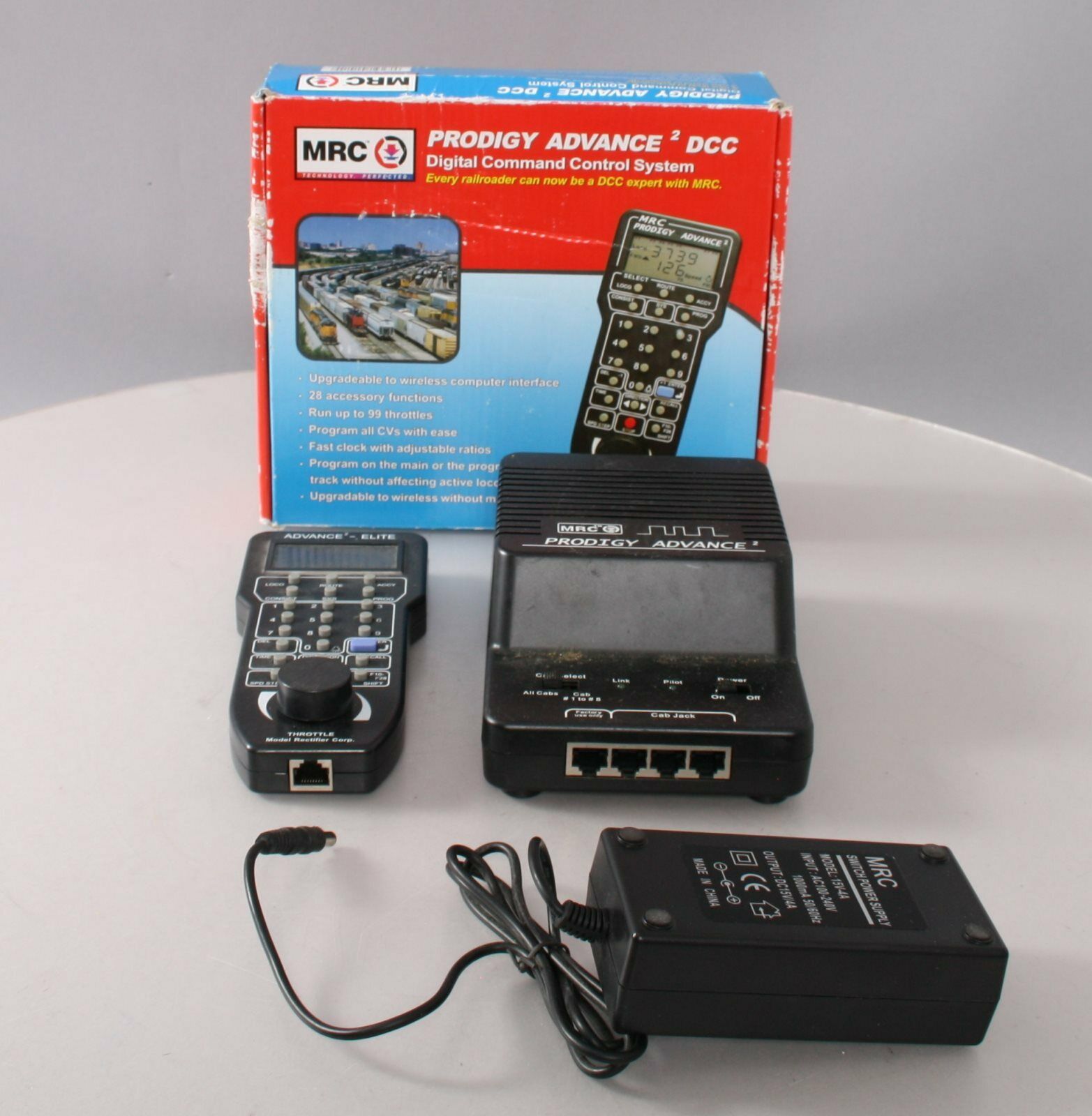
Otherwise you'll want to change the road number. This will be a little different on each system, but it's often the only programming you'll ever have to do. Some stores (online or brick and mortar) will set this for you if you ask. Otherwise I'll use the MRC system as an example. No need to connect a programming track, you'll do this on the main. Just make sure there is only one locomotive on the track with the default number of "3."
  1. Press Prog
  2. Select Prog Main Track
  3. Press Enter
  4. Type "3" to select locomotive No. 3
  5. Press Enter
  6. Adr will flash on the screen
  7. Type the number that you want to use for that locomotive (usually the road number).
  8. Press Enter
Although another option will flash in the screen, if all you are doing is changing the locomotive number, then just press Loco, type in the new road number to select it, then press Enter. You are now ready to run that locomotive under that number.

For the majority of modelers, it doesn't need to get any more complicated than that. However, there are many other features that DCC offers that you can't do easily, or at all, with DC. This includes things like consisting, sound, speed matching, tweaking motor performance, etc. I'm not going to say that these are all simple, and some systems are better than others in these regards.

Myth No. 2 - Wiring is Complicated

I'm sure we're all familiar with the, "DCC only needs two wires," marketing copy. While it's technically correct, in practice you'll probably want to do a bit more. The bottom line is, if the wiring is sufficient for reliable running under DC, then it is for DCC too. But I have a few comments:

DC can often be far more complex to wire than DCC. This arises when you want to be able to run multiple trains independently at the same time. So you have to create different electrical blocks, with separate controllers, etc. 

With DCC you'll need multiple throttles as well, but you don't need to wire in blocks for independent running. This is one of the biggest advantages in my opinion. It's often described as, "controlling the train, not the layout." In other words, you don't have to worry about flipping switches on the layout, or not running into a block controlled by another throttle as you might with DC. You just choose your locomotive and run it.

You might use separate blocks to install circuit breakers in case somebody causes a short (a derailment, for example) in one section of the layout. By doing this, that short won't shut down other sections of the layout. But it's not required.

It's also much easier to wire a reversing loop in DCC. With DC you usually have a manual switch (although there are options to automate it). But there are more options with DCC.

Some other areas you'll often see mentioned are using boosters. A booster is needed only when you are drawing too much voltage. That's determined by the number of locomotives and how much each locomotive draws. The number of boosters doesn't have anything to do with the size of the layout itself. a 4' x 8' or 40' x 80' layout can both be run on a single booster. If you're considering DCC, start with one and see what your actual usage requires. 

Then there's the idea of "DCC Friendly" switches. This isn't a defined term, so it means different things to different people. Switches should generally not be wired for power routing. Some use it to refer to whether the frog is powered or not. Another common description is when the points are electrically connected. All of these situations will work for DCC. 

If your layout is already built, then yes, there may be some alterations that you might choose to make. The advantage to a powered frog is the same as DC, it prevents stalling (particularly for small wheelbase locomotives). I'd recommend that the points should be electrically isolated whether DC or DCC, but they will work with either.

But if you have a fully wired DC system, with blocks, etc., then converting is certainly something that may require some work. In fact, for a reasonably large existing layout I would consider this a more valid reason to not convert than probably any other. 

Myth No. 3 - It's Expensive

Obviously, "expensive" is a relative term, so what you consider is expensive, somebody else may not. So instead let's say, "it costs money."

Unless you have a fixed budget for all the money that you will ever spend on your layout in your lifetime, the question isn't about how much it costs, but whether you'd prefer to spend the money on something else. You could buy several more freight cars, or get a DCC system. Get a new locomotive, or install a decoder in one or more existing ones. 

Certainly if you have a large roster of locomotives, then converting them all to DCC may be a considerable expense. If you actually use all of those locomotives on a regular basis, then this may be a very reasonable reason not to switch. Having said that, I've known plenty of people with extensive rosters that have used a number of approaches to switch.

In my observation and experience in this (and other) hobbies, people will spend money on something if they want it enough. If DCC doesn't reach the level of "want it enough" then you probably won't spend the money on it. 

That's really the reason why people don't switch - they don't think the potential benefits are worth spending their time and/or money on. "It's too expensive," is really, "it's not worth that to me."

The fact is, the DCC system will usually cost less than the benchwork. Or the track. There's a good chance that it's less expensive than the switches and wiring needed for a complex DC block system. Or many other things. If you consider what you'll spend on your layout over a lifetime, a DCC system isn't going to rise to the level of a "major" expense. So you'd rather spend the money on something else. Nothing wrong with that.

Myth No. 4 - "DCC Ready" Means Something

"DCC Ready" is a marketing term. It is not defined, and thus can mean something different to every manufacturer. There are two general categories, though.

Newer models, that were released in DC and DCC versions in their initial run, generally just need a decoder added. Those that were initially released with sound may even already have a speaker installed. Regardless, they were designed with a place for the decoder (and for sound units, a speaker). This makes it very simple to upgrade.

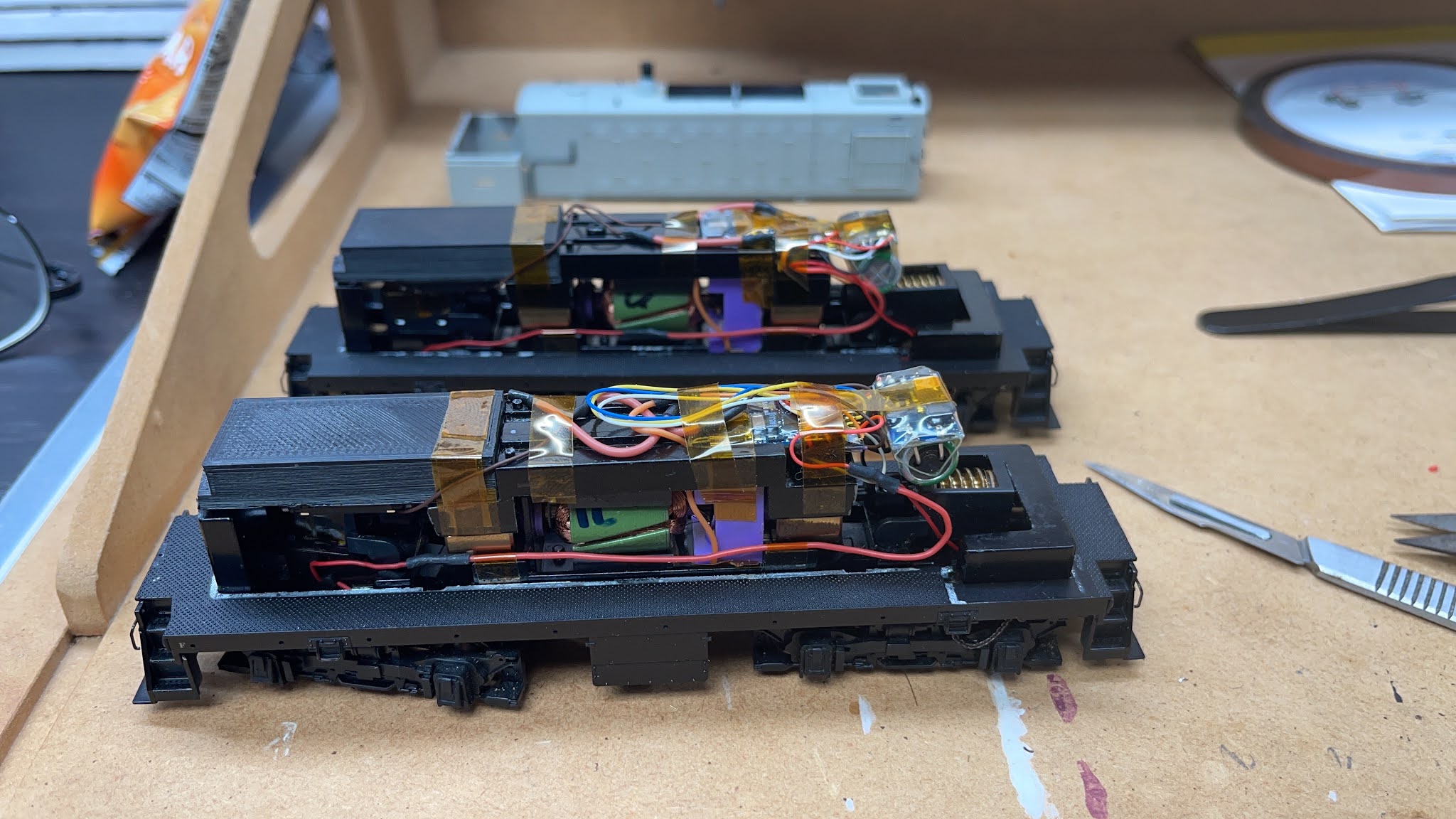
Older models, that weren't initially designed for DCC, can be more complicated. I've purchased "drop-in" decoders for a "DCC Ready" model that required some modification of the frame to fit. I've had others that required you to cut several traces on the circuit board when you install a decoder. 

I usually remove any circuit boards when converting an older model.

The fact is, any locomotive can be converted to DCC. But older ones can be somewhat complicated. My advice is to plan on paying somebody to install a decoder if it's an older model, regardless of whether it's "DCC Ready." If you learn how to do it, or it's a simple installation, then all the better. And sometimes "paying somebody" is working on something else for a buddy who installs a decoder for you.

DC(C) Works for Me

This is not a myth.

If DC works for you, then great! It's worked for decades and will continue to do so. I do understand that if you are happy and continue to use DC that you'll be subjected to a lot of people trying to convince you to switch. Again, that's not my intention here, but on the flip side I do think most people will find operating with DCC "better" and want to help dispel the myths that might prevent you from switching.

I would recommend that if you prefer it, then don't bother justifying why. If you say, "it's too expensive," then somebody will try to prove to you that it's not expensive, and may actually cost less than the DC system you're building. 

Just tell people you're quite happy with how it's working for you, and it's what you're using now. In particular, I wouldn't say the reason you are sticking with DC is one of the ones that I've listed, because many folks will see that as an invitation to dispute that myth. 

It really doesn't matter why somebody chooses to use DC or DCC.

Why DCC?

Like I said, this post isn't intended to promote DCC over DC, but I think it might be useful to know why I use it. This is probably more for new modelers rather than those who have used DC for a while and are happy with how it works for them. But for those on the fence, or new to the hobby, why consider it at all if it will cost more for a DCC locomotive than DC?

I mentioned several advantages like independent control of locomotives, consisting, motor control, etc.  Overall, I think DCC is more flexible, and offers many features that DC just doesn't. The ease of installation (of the system, not decoders in locomotives), are all reasons for me. As a prototype modeler, I want my model railroad to operate like the prototype as well. This includes how the locomotives move, things like sound (because the use of the bell/horn and a number of other features) is important for actual operations. But that's me.

But the No. 1 reason why I prefer DCC is its ease of operation.

Most of the reasons that people give for not switching to DCC are focused on the layout owner. This makes some sense, since it's their layout and they are paying for it. But as somebody who has operated on dozens of layouts, I can tell you that it is absolutely the best option for operating somebody else's layout.

I can go to a layout that operates using DCC and immediately know how to run my train. I've also operated on a number of DC layouts, and it's always a much more complicated process. For the layout owner, who is used to their particular block and control design, it may seem simple, but for a visiting operator that's usually not the case.

With DCC all I need to know is the road number (or consist number), select a loco, and run my train. It's the same on every DCC system. 

This is also one of the main reasons I love the ProtoThrottle. It's very intuitive, and simple. I'm also not interested in more "advanced" DCC capabilities. For example, I've operated on layouts where turnouts were controlled by DCC. This is fine if everything is operated by a Dispatcher, but not if each operator is expected to control switches from their throttle. 

Like DC, the layout owner will say, "it's easy." But I find that in both cases we spend more time asking for help in getting the layout to work when I'd prefer that my focus (as an engineer) is on my train. I appreciate it from a technology standpoint. But I don't want to use it. 

I want it to be simple for operators coming to my layout.

What System?

If you do decide to go with DCC, obviously, I'd recommend MRC, which I've been using for over a decade, although I'll be switching to ProtoThrottles for the actual throttle. So any base system that works with them is fine with me.


But when asked which system I recommend, the answer always starts with whatever your modeling buddies use. They will be your first point of technical support, and can also bring throttles over so you don't have to buy several at once. Around here that would be NCE. I'm comfortable going my own way, so will stick with MRC. I'm not a fan of the Digitrax design, but they are also a very capable system. Outside of the "big three" there are varying degrees of features, flexibility, and complexity and you'd have to be willing to go that route knowing that you many not know anybody else that uses that system. Although I think a lot fewer modelers use MRC, I can say that I know it is a fully capable system, like NCE and Digitrax. On the other hand, I've never used something like the Bachmann system, so I can't tell you if it has all of the core features I'd expect.

Each system does have its strengths, and since I'm not familiar with all of the latest features of all of the many systems, I'm not really qualified to answer anything more than that generalization. 

Thursday, October 8, 2020

Layout Progress - Circuit Breakers and Fast Clocks

This is the sort of work that I don't do nearly as well as I'd like, it's time consuming, takes me longer than it probably should, but it's got to get done.

I've been working on the sheet rock, the benchwork for the bulk tracks on the wall opposite Whiting St Yard, and painted the door New Haven #292 Warm Orange:

Like the rest of the basement, the walls will be New Haven #246 Silver Gray and the trim is New Haven #212 Hunter Green. I simply take the paint chips for the New Haven Color Guide (available from NHRHTA) and have Home Depot match the colors. Oddly, their machine was unable to match the Hunter Green this time.. Too dark they said. Fortunately, they had matched it for me 10 years ago, and I brought in a piece of trim that I had already painted and they were able to match that.

I'm also trying to engineer the swing bridge (my preference) or lift out to connect the bulk tracks to Whiting St Yard. I have the materials to install the grid for the drop ceiling too, so the room is coming together quite well, if slowly.

Wiring Circuit Breakers

While the construction is continuing, I've also completed some more interesting projects. These go much faster...

As I noted in a prior post, I ran a new bus line all the way around the room to allow both parts of the Berlin Line to be in the same electrical block. The lift out is where the two sections meet, but I didn't want to make an electrical connection across the lift out since that would require plugging/unplugging wires to operate and it's across the only entrance/exit to the basement.

So I decided to figure out where I'd place the remaining circuit breakers, and rewire for those.

I had originally installed a switch to allow DCC or DC use, but now that I'm installing the PSX circuit breakers, it was time to finally remove the DC option. I mounted the circuit breakers for the main deck and the staging deck on the wall between the two.


This seemed like the best place to keep it out of the way, but accessible. To do so I used some scrap 1" x 3" lumber drilled into the studs, so I could mount the boards to a piece of Masonite across those, leaving space behind the board for wires.

Fun fact: the piece of Masonite was the test piece to see if it would work for building the helix. I glued two small lips (3/4" strips of Masonite) to stiffen it, and brought it to the NE Proto Meet and showed it to Bill, who immediately said, "I know what that's for!" He agreed that it looked like it should work, and I moved on from there. In this case, it was a scrap piece just the right length to span this location.

The main power comes up from the MRC Prodigy Advance unit on the shelf below, behind the board, and comes down to the input on the top left of the upper PSX circuit breaker. There are short connectors to the board below it, and then the output on the bottom left goes behind the board again, then up to run under the upper deck. This required yet another bus that I just ran to provide the power to the Stanley Works and Berlin Line. Between the center of the layout and the Stanley/Berlin Line circuit breakers there are three bus lines under the upper deck - the upper deck bus, the bus to the circuit breakers, and then the bus back from the circuit breakers to get to the other half of the Berlin Line. 

The right outputs go to the upper deck (upper PSX), and staging deck (lower PSX). Very simple, actually, and mostly required repositioning the existing wiring and allowed me to eliminate the DC/DCC switch I had installed.

Behind the agent's desk are the PSX boards for Stanley Works (top) and Berlin Line (bottom):


Access is through a window I cut in the utility room wall, which also provides better airflow to the furnace (which is needed). The input is the upper left, and the two boards are connected on the left. I haven't run the new Stanley Bus yet. The two wires to the left of the boards are the Berlin Line which will connect to the output of the lower PSX.

I tested them all, and power is flowing to the circuit breakers and not shorting. All of the feeders are ready to be soldered on the Berlin Line. I'm getting started drilling and pulling feeders for Stanley Works and the east and west sides of town. I'm also completing some track adjustments in staging.

To the left of the window the Berlin Line bus is connected to two terminal blocks, because I needed to run a bus to the three (!) different sections of the Berlin Line:


You can see that one of the bus lines goes back through the window, and then circles the entire room to get to the Berlin Line. The others connect to Whiting St Yard and the bulk tracks.

My initial plan was to separate the main line into its own circuit, but it's really not necessary. I still have to cut gaps for the different blocks as well. But I have 4 blocks now for short protection:
  1. New Britain. This is the main deck, from just before you exit the top of the helix from Hartford, to just after you enter the helix toward Plainville. 
  2. Berlin Line. This will keep the two switching crews in separate blocks for a lot of the session. This starts just east of Elm St on the Berlin Line, to the end of the Berlin Line Staging.
  3. Stanley Works. Again, this keeps this crew entirely independent electrically from the others.
  4. Staging. This includes the helixes.
The goal is to largely isolate each crew electrically so that if one causes a short, it won't affect the other crews. There will be times when both switching crews are working parts of New Britain (I think), and two crews will operate in the same block for through trains. But for probably 80% of the session, each crew is isolated electrically.

Installing Fast Clocks

Another project that has been a long time coming is to install fast clocks. I've looked at a number of options, but the key for me is that I wanted analog clocks. So I'm using the FCC4 by Mike Dodd. (He has a great website for his model of the Virginian too, although unfortunately it was dismantled when they moved. He is working on a new one.)

It's a pretty simple system. There's a controller, you can wire some switches for additional control to it, and then use modified quartz clock movements installed in cheap clocks. You can purchase the controller as a kit, and he also shows you how to modify the movements yourself, or you can buy them preassembled by Mike, which is what I did. I've had them for some time, and had a number of clocks ready to convert.

I installed the controller next to the PSX circuit breakers, and used a surface mount electrical box to house the switches. The upper left turns the power to the system on/off. The upper right starts and stops the clocks. The lower left is a fast forward switch (which causes them to run 17x faster than normal), and the push button resets all the clocks to your start time. There are dip switches on the circuit board to change the fast clock ratio, for now I have it set at 4:1, I might experiment with 3:1 as well.


Right now I have one clock I built into the fascia at the station:


There's a second clock at the agent's desk:


It also conveniently hides the seam between the two pieces of plywood. 

I installed a larger wall clock next to where the phone will be at Whiting St. Yard:


The square hole is where I'll run the wires behind the phone. This one is behind the door if it's open, but I don't anticipate having that door open during sessions unless somebody needs to go into staging for some reason.

I needed to order another movement and a couple of sets of hands. Once those arrive, I'll install one above the other desk, plus one in the center of the staging level. Basically I want at least one visible from all of the common operating locations. Since the staging will probably be behind a skirt/curtain, they'll need one. And if the crew is using the desk to work on paperwork, they'll have one right there as well.

The system supports up to 15 clocks. I have three of the smaller ones that I haven't used yet, and when we get to the next shakedown session I'll see if we need to put up a few more. I'm thinking that maybe I'll need one near Stanley Works, although they do have a clear view to the one at the station.

Thursday, August 6, 2020

Modeling NY/YN Freights - DERS-2b (RS-2) 0502 and 0503 - Part III

Here are links to Part I and Part II of this series of posts on modeling the NH DERS-2b (RS-2) locomotives.

I covered the pilot grab irons in Part I (although I've started using the jewelers pliers to make the curved bends since it's easier to be consistent), but one of the most challenging parts of identifying what needs to be done is the additions to the pilot that the New Haven made. There are similar modifications to the DERS-1b (RS-1) and DERS-2c (RS-3), but each class has a different configuration.

My original plan was to use the Custom Finishing part #347 RS-2 End Platform Railing Mounted MU hoses. However, closer examination showed that it wasn't an accurate representation.

Here's a picture of 0502 in Pittsfield in c1947/8. You can see that there are two MU receptacles, along with some air hoses mounted on the end railing. Two pipes run down the front of the pilot and work around the buffer. But it looks like there is another pipe of some sort behind the railing, just to the left of center.


It was the builders photo that clarified that for me. This is 0500.

First, you'll notice that the air hoses weren't installed by Alco, at least prior to this builder's photo. But you can see (particularly if you look at the left end railing), that the MU stands are the pipes that go down into the walkway, just left and right of center.

The air hoses are bent to come in front of the end railing just below the MU receptacles, and the piping is then bent to go to the left of the buffer, and then have elbows connecting them to pipes behind the pilot.

Because these were equipped for passenger service, they also had BARCO steam line pipes. You can see it sticking out of the door beneath the coupler.

Mike Robbins has a photo here that clearly shows the set of doors beneath the coupler, and the BARCO steam line. You can also see how the air lines and other pilot details.

He has another photo, that shows the pilot details even better. I also used this photo to identify details below the walkway on this engineer's side of the locomotive. It also shows the brake equalizer (?) in great detail mounted on the box behind the engineer.

The second group of RS-2s, 0510-0516, delivered in November and December 1948 had the piping routed down through the walkway, there is a single MU receptacle, and also looks like they didn't have the doors over the BARCO air hose, as seen in this Sweetland photo of 0516 in 1954:


Looking more closely, the end railings are also attached differently than the original delivery, and the uncoupling lever is longer too. These better match the model, but because the railing are so fine and well rendered on the P1k model, I decided not to replace them (I tried though!). I don't have a builders' photo of the second group handy, to see how they were delivered from Alco. 

Since 0502 and 0503 are from the first delivery, I'll need the dual MU receptacles and to have the piping visible on the pilot. So instead of using the Custom Finishing part, I cobbled together the ends from several parts. 

First, the Kato end railings have the correct MU receptacles (minus the piping that goes into the walkway). I considered using them as is, but the Proto railings are significantly thinner and better looking. So instead I cut the MU receptacles off of the Kato end railings, and glued them to the Proto ones.

This is the Kato end, showing where I made the cuts.
I then filed the back of the part to eliminate the portion of the railing, and to thin the part.
This is the Proto end with the MU receptacles and wires bent and installed.

On the back I used .030" styrene rod, and bent the end to represent the MU pipes. In reality, there are more rectangular box-like structures at the top, but I didn't take the time to figure out a way to make those.

The next step was to bend the wires and cut them to go around where the buffer will be, then cut to length. It was trickier than I expected.


Precision Scale elbows and Hi-Tech Details rubber air hoses completed the end railing details. The rubber air-hoses take ACC very well, attaching pretty much instantly to the brass elbows. 


Next up were uncoupling levers. I originally started with the Kato ones, since they have the correct brackets. However, I found it very difficult to measure and drill holes in the precise locations needed for the one-piece part. 

So I decided the try the new Cal Scale Coupler Lift Bar Mount Brackets. I already had some Detail Associates Uncoupling Levers. I believe the brackets are from the forthcoming RS-3 models. They are tiny, and have two mounting pins. However, I didn't think I could drill that many holes that accurately, so I cut off one of the mounting pins, and installed it so the mounting pin went into a hole underneath the lever. The bracket fits over the bar and with styrene cement, the second pin isn't necessary. Because they are separate parts, you don't have to be as precise with your drilling.


I also added the Cal Scale poling pockets. Since I've seen the air hoses pulled to the side, and also left to hang, I modeled this one with the hoses just hanging.

I will complete the buffer once the walkway is installed on the chassis, since I'll have to build it around the coupler box. There's also a second stiffening piece of strap steel (which looks like where the piping was attached on the back side) above the receptacles. I missed it here, but added them later. 

Next up was the brake equalization lever. Thanks to that photo, I was able to see how to best mount the part (it's not really an exact match but it looks good), and also add some additional piping.


It's .010" wire, except for the short piece beneath the elbow which is .020" wire. I cut a small piece of .030" styrene rod and even a tiny triangle for the bracket next to it. I think the extra piping helps tie it into the model. I also tried to carve out the square-shaped hole on the front of the styrene rod (I couldn't find a part...)

I've also attached the railing so I could paint everything black. I'll brush paint the front and side of the box Hunter Green.


Parts Used in this post:
The model is a Life-Like Proto 1000 (now Walthers Proto) RS-2

Cal Scale (order from Bowser Trains)
190-734 Poling Pockets
190-729 Loco Coupler Lift Bar Mounting Brackets

Custom Finishing Models (order direct)
308 Brake Equalization Valve

Detail Associates (eBay or old stock at hobby stores)
2205 Diesel Uncoupling Levers
I had them on-hand, otherwise I would have used Cal Scale 190-514 Coupler Lift Bar

Hi-Tech Details (order direct and can be found in hobby stores)
HTD-6038 22" A.A.R. Air Hoses

Kato (eBay)
Just the MU receptacles from the RS-2 end railings. The handrail set is out of stock at Kato. Otherwise I would have made the steel strap from styrene and used the Cal Scale 190-618 MU Receptacle Set or Detail Associates 1507 (or several similar ones that come with these parts)
 
Precision Scale (eBay, local hobby store or direct with $25 minimum)
48395 Elbows (0.020")
 

Oops. That's not an RS-2...where did that come from?!?