Showing posts with label Trackwork. Show all posts

Wednesday, February 19, 2025

Fiddling

Progress is one of those things that I think we all struggle with from time to time.  Tom Jacobs has his "hour a day" mantra and Chris Adams has "do one thing." Similar approaches are great ways to keep things moving.

My approach is similar, but in an ADHD bent rather than an OCD sort of way.  What's the difference? Chris and Tom get more things completed.

Rather than try to force myself to do those things that I should be doing, I've gone back to doing whatever I gravitate to instead. Lately that has been fiddling around with freight car kits. Cleaning flash off resin kits, drilling holes, etc. are great mindless things when my brain has had enough, but I want to keep busy. That has led to assembling some bodies and doing some of the detail work when a particular kit captures my interest. 

This leads to lots of projects in progress, but my theory is that they will all get finished eventually.  Progress is progress, after all. There is a bit of method to my madness, though.  When I start doing a particular task, such as cleaning flash or drilling holes, it's easy to just keep moving forward with that task.  Thus, pulling several kits (often with a theme) and completing the process on several.

In addition to getting to see the cool kits I've picked out over the years as important to my layout, right now it's a better approach for me.  Changes in work has left me more mentally fatigued than short on time. These more mindless tasks are good distractions, but also let me give my brain a rest.  The reality is, for me anyway, that my brain becomes more productive and finds solutions best when I don't think about them. So this approach ends up being helpful for my work and my modeling. The apparent chaos can be a good thing.

The big thing here is that, as a hobby, it's supposed to not only be fun, but engaging. It's a distraction from the rest of life, and a better one (at least for me) than just watching TV or videos online (I've done way too much of that already).  It's also a way of accomplishing things that are uniquely you.  Leaning into my nature has already made me far more productive, and I have already found solutions to some of the things that have been holding me back on those things that I should do.  As a result, I do want to complete a number of these works in progress, and get to a few critical things to get the layout fully operational again, and set up in a way that I can be prepared for regular sessions. And scenery.

So what have I been working on?

Rapido 44-tonners


Various Box Car Mini-kits and Kitbashes

Ballast and Cinders experiments

Painting and Weathering Ties Experiments

Resin Gondola Kits

Resin Reefer Kits

Reorganizing

Wednesday, February 22, 2023

No Rail Joiners

These are KV Models compromise joint bars. On the left is Microengineering Code 55 track, and the right is a Peco Code 83 curved turnout. The KV Models joint bars can be soldered to the rail, so I figured I could go a step further and eliminate the rail joiners at the same time.

You can also see one of the reasons I personally don't care for Peco track and turnouts - their tie plates and spikes are significantly larger (out-of-scale) than Microengineering. I'll be able to reduce this with painting and weathering and, of course, it would be less noticeable on a layout that is all Peco track.

Although I'm not doing this everywhere, I am using the approach throughout New Britain Yard and other newly replaced track that will be close to the fascia. Especially in cases like this where the rail code is different.

The basic process I'm using now:

  1. Use a Dremel with a wire brush to polish the backs of the joint bars while still on the fret.
  2. Tin the backs of the joint bars while still on the fret.
  3. Clean/use a Dremel with a brush to polish the rail.
  4. Apply flux to both sides of the rail.
  5. Apply solder paste to both sides of the rail.
  6. Apply solder paste to the back of the joint bars while still on the fret.
  7. Cut the joint bars from the fret and apply to both sides of the rail.
  8. I lightly squeeze the joint bars with a pair of tweezers in place, then touch the iron to the top of the rail.

I polished and tinned the entire fret at one time. I apply the solder paste only to joint bar just prior to cutting off the fret to install. The flux/solder paste is sufficient to hold the joint bar in place in the web of the rail, I squeeze them just to ensure they are securely soldered to the rail web. The extra tie in the photo above was to raise the Code 55 rail into the correct position. In addition to the shorter rail, Microengineering ties are shorter than Peco.

This is the only Peco turnout on the layout, and I have four Walthers turnouts too. Despite the enormous flexibility in modifying Microengineering turnouts, they can't be used for everything. The track geometry here needed a 28" radius diverging track, which is a close match for the Peco turnout. The Walthers ones are also on this track around the top of the helix for similar reasons.

Wednesday, March 23, 2022

Progress: More Trackwork

Coming around the helix you and you'll be at the start of what is continuous industries. I've made a few modifications here. The two tracks in the front of the photo with the hopper and the tank car are Hardware City Fuel. I moved these over to make room for one additional track, for the City of New Britain, with a chlorine tank car. 

The more obvious change is the addition of two tracks connected to Track No. 5 on the far side of the main tracks. These are DK Coal and Miner, Read, and Tullock. I had been postponing these because of the diamond crossing in the middle of them. I used another of the new Walthers turnouts (24' and 20" radius curved) for Miner, Read and Tullock.

The 30-degree crossing is from the excellent new Diamond Line from Fast Tracks. 

While it probably needed a different angle, and at least one of the tracks curved through the crossing, I didn't want to handlay this one. Not just because of the challenge, but this product is the first that actually looks like a prototypical crossing, with cast parts. 

I deviated from the design, though. It comes with pieces of rail that you install and then solder to PC board ties at the far end to keep everything in gauge. Instead, I trimmed away the last few wood ties and removed several ties from Microengineering flex track, then slid the rail into place in the castings. The ME track keeps itself in gauge, and it also let me curve the tracks right up to the frogs.


I'll fill the gaps with styrene. I need to get a Dual Frog Juicer or some other autoreverser to power the two inner frogs.


If these were available when I built the tracks for Shurberg and New Britain Lumber, I definitely would have used one. But that is set quite a distance away from the fascia and is already in place. I'll look at potentially changing it, but I don't think I will at this stage.

In this section, the only track that needs to be completed now is the Stanley Svea track that extends past the Household Fuel silos and onto a curved trestle. It won't stop me from being able to operate, but I'd like to finish that relatively soon too.

Wednesday, March 9, 2022

Progress: Trackwork

Finishing up the trackwork. I've frequently said, "don't be afraid to make changes."

Well...

Track No. 5 - First Modification

A few years ago, I extended Track No. 5 coming into the main portion of the layout. The initial idea was to extend the track as far as I could and provide a point where the eastbound freights could shove a cut of cars. To do this required creating a level track because it's at a point where the helix is already descending. It also gave me an opportunity to put in a nice retaining wall for the track separation.

When I later made modifications to the backdrop so I could include more industries on the north side of the tracks, it also meant I could more easily include the East Main St. crossing. 

Track No. 5 - Second Modification

The problem was now that there was only room for 2-3 cars before the East Main St. crossing. Either the freights would have to shove the freights all the way past E. Main, meaning the rest of the track was pointless, or I needed to find a different solution.

I decided to install a new entrance to Track No. 5 so that it would start just to the west of East Main. That left a portion of this track for an industry.


The plan was to use that for United Coal Co. In this section of town there are a lot of coal dealers, and there will be D&K Coal right across East Main St. In fact, in this section of about a half mile there were six.

Track No.5 - Third Modification

This industry would be tough to fit, though. In addition, it would be serviced right off the Main, instead of off of Track No. 5 like it should be. It's also the only industry track in this section leading into the helix, and it's also in a narrow aisle between the two helixes where the Stanley Crew is normally working. Not a great setup. Out it comes.


Track No. 5 - Fourth Modification

Shortly after I did, I was working on the industrial tracks on the north side of the main tracks when I realized that the crews would have to enter the main to work one of the industries. At this point, if Track No. 5 were extended, it would operate as a lead for the industry. In addition, the crew could come all the way from the yard on Track No. 5 and not need to enter the main at all. This is, of course, also prototypical. It just extended further for several other industries before connecting to the main.

This doesn't need to be level, and ideally the turnout shouldn't be as far around the helix (although it will still be on the back side). I suspect it will be rare for the crews to use it, though.

As far as cuts of cars? I've decided they'll just have to use the portion starting at the crossover. This should be long enough and will have to do since I can't install the full length of Track No. 5. The reality is, eastbound trains really left their cars on the west side of town, on a track about a mile from the yard. Since that entire portion doesn't exist on my layout, it's a compromise no matter where I spot the cars.


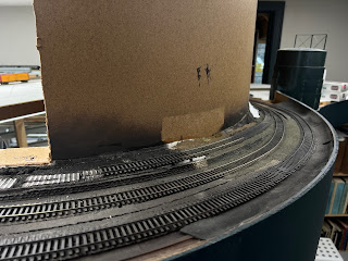
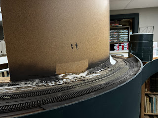
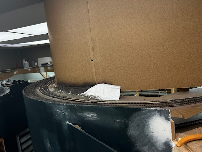
Working backwards from the turnout for the first industry, I used a full piece of flex track for the lead, which determined the placement where Track No. 5 will now start. Although I really liked the retaining wall, it was tough to get that extra vertical grade smooth from the end of the turnout to the top of the level portion. With this turnout closer to East Main St., it would need to have been redone anyway.

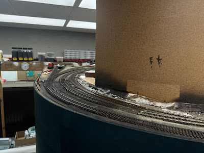
Here's looking toward New Britain, and it what you see when entering the main portion of the layout now. I also reconfigured the two tracks for Hardware City Fuel to allow space for the New Britain City Works track (to receive chlorine tank cars, among other things). More to come.
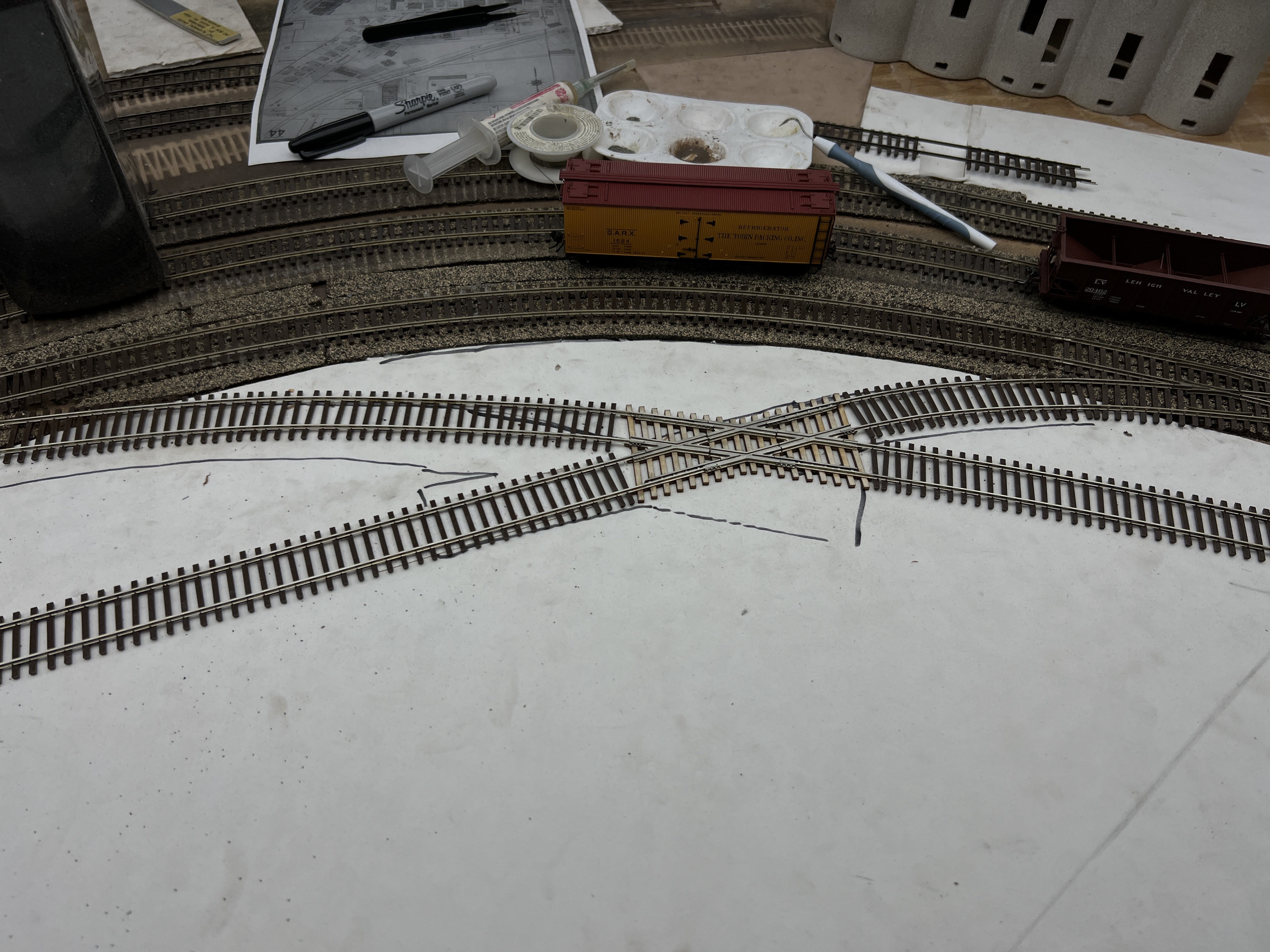

Walthers Turnouts

The two turnouts in this location were the old Shinohara/Walthers ones. I needed curved turnouts with a 26" or 28" outer radius. I could have handlaid them, but these were much faster. The two primary issues I have with them is that they are Code 100, and the points aren't sprung. Obviously, the details themselves are nowhere close to Microengineering, but I felt that based on the location I could live with that.

But Walthers just released their new version. They are Code 83 and have sprung points. Like the old ones they are 28" outer radius and 24" inner. Although that 24" is less than my mainline minimum of 26" they have been well tested in this location and have worked fine with my equipment.

I also picked up one with a 24"/20" radius for the industry track coming off of Track No. 5 (which, not being the main track, has a radius of 24"). 

Overall I think the Walthers turnouts are decent. For most modelers they will work well, although if you're particular about accuracy, not so much. The spikes are still quite large. Also, since they made the points out of continuous rail there are sections of the ties that have no wood grain.

I also found it odd that on a brand new track product that first thing you have to do to install it is remove the first tie at the end of each track (and then they recommend purchasing their extra ties). Microengineering has a tie that's slightly shorter, and has no spikes so you don't have to remove any ties. At the very least they could have designed it so it didn't have that final tie (even better would be to include three of the extra scenic ties too).

There are holes for spikes. Most are between the molded spikes next to the rail. So the placement is better, but there are still a bunch of holes if you don't spike/nail your track. A better option would be dimples on the bottom of the ties to drill out if you choose to go that route. That has been done before too.

While a lot of people will like the continuous rail points and it's appropriate for a lot of modern track, it's not accurate for my era. The rail is thinned as it gets to the end, which means it flexes too much to flip the points by a finger if you aren't close enough to the throwbar.

I would have liked to see them put a little effort into making them more accurately, and finer details overall. That's primarily a research/design thing and wouldn't have added any cost to the tooling.

The diverging rails are electrically connected to the stock rails, and with continuous rail points there won't be a concern for losing conductivity. The frog is dead, but there are two places (one underneath, one to the side of a tie) to power it if you'd like.

Mechanically they are decent and I don't have any concerns in that regard. But the overall design in terms of details and certain things, like the need to remove a tie, feels a lot more like a product designed 20-30 years ago. Not something I'd choose to build a layout with, but good enough for a few special needs.

Sunday, November 28, 2021

Rail Length


Getting ready to move a pile of rail from here to there at Depot St. I walked about 3 miles around the circumference of a 20’ radius circle in an afternoon.

What I also found interesting is the ratio we were moving. It was rolled in 1915 and 1922 for the NH, 107 lb rail taken out of the Canal Line near the Massachusetts border.

New Haven Rail

What’s the length of a piece of rail? The conventional knowledge is 39-feet, so it would fit in 40-foot gondolas. While that is true, 40-foot gondolas weren’t always the standard length pre-depression. In addition the surveying, real estate, and railroad industries use some standard systems of measurement.

These rails are two rods long, or 33-feet long, a rod being 16.5-feet. Of course, that worked well since it fit in 36-foot cars. The NH didn’t have 40’ gondolas (or flat cars) until the 58000-series of gondolas were built in 1929. (For more on those, including a diagram, see this post.) So they may have continued to receive 33-foot rail until those cars were built.

The 16.5-foot rod is related to other measurements - a chain is 4 rods (66-feet), a furlong is 10 chains (660 feet), and a statute mile is 80 chains. The surveyors’ chain is just that. A chain with 66 foot long links.

So for those modeling earlier eras (pre-depression to a large degree), it may be more appropriate to put those joint bars every 33 feet instead of 39 feet. This is appropriate on some lines even today, large portions of the CNZR is CNE/NH rail from pre-1926, the oldest I think from 1896-7. The Highland Line is still largely 107 lb NH rail, so I’ll have to go take a closer look at when it was produced. I suspect that I’ll need to go with that measurement on the layout.


Friday, October 15, 2021

Rail Fanning - Switches

While at work I get the chance to do a lot of rail fanning.  That is, I get to study the rail and track.

Along Savin St. is a switch for a side track, currently not in use, but still called the Roger Sherman switch/track for a former industry. I will be (semi) handlaying a turnout soon, and also installing the two turnouts for the bulk tracks. So I decided to take some reference photos to prepare for the project. 

It's a left-hand switch, and there are many things we can document and learn. To start, there are two throwbars (actually, one spreader bar and one throwbar if my terminology is correct).

This is consistent with what I've seen in photos on the New Haven.


Here's a crop of the Jim Karl photo for comparison. To start, the New Haven photo has a joint with four bolts in the center of them. Otherwise basically the same.


The points have the manufacturer as well as 107 NH notated. They were made by Wharton in August, 1958. The 107 refers to the rail size (107 lb, which was the most common NH size), and was cast for the NH. The 15 refers to the switch (points) length in feet.

Most likely the track side track was installed in 1958, but it also highlights how switches might use heavier rail than the track in service. Code 55 switches are hard to come by, but you could use Code 55 track and Code 70 switches for a light branch line like this.


Here's another view, and you can see that the braces were also made by Wharton. 


Note that the points themselves are reinforced on both sides, and ground for a tight fit.


You can see how they fit over the base of the rail, and the stock rail is slightly ground down so it "nests" against the stock rail.


While I could file points down in a similar manner, Proto87 Stores sells them ready to go. I don't bother replacing the Microengineering ones, but for handlaid track, they are what I use.

The switch stand is the same model I have in my front yard, and is conveniently a close match to one of the ones by Rapido.


It's interesting that there aren't heel blocks. I added them to one of my turnouts, but not having to will save me time.


One interesting detail is a gauge rod for the diverging track. Forming these out of stiff wire (like piano wire) would actually function for handlaid track.


Although I don't have any way to measure it, this is a very sharp diverging track. It turns out there are 9 gauge bars along this short section. Dale said it's a sharp enough radius that they have difficulty getting cars to couple. The couplers will line up, but the pin won't drop. You can also see how worn the inside of the rail is from the flanges.


The rail in this section is still very old 79 lb rail manufactured in 1899. Some sections of rail are dated 1897. But the switch is 107 lb rail, so there are compromise bars at either end. 


The manufacturing marks have largely worn off, but you can see 107 NH on one, and 78 on the other. I've been told the NH used 78 lb and CNE used 79 lb, and based on the info in my earlier post there are very minor differences:

Head Width: 2-16/32" vs 2-6/8"
Rail Height: 4-3/4" for both
Base Width: 5" vs 4-3/4"


Looking at the frog, it's a manganese rail bound frog. I haven't researched the details, just know what it looks like. 


It also conveniently tells us it was manufactured by Racor, is a No. 10 frog for 107 lb rail on the NH. I prefer a cast or model frog to filing your own since it lacks much of the detail. The Microengineering ones look very good. For handlaid I like the Proto87 Stores ones.


The information noted, 15' foot long switch points for a No. 10 switch, matches the data in the book I have. These are in the order they appear in the book.


As a last look at my post on rail codes, for the Cottage Grove Road grade crossing, 131 lb. rail was used. But there isn't a compromise joint bar to go from 78/79 to 131 lb, so a short section of 107 lb rail was used to bridge them. So this picture conveniently has 79 (code 55), 107 (code 70) and 131 (code 83) rail so you can see how they differ in size.