I thought that the finished product would have far more impact than the build-up...
While we have discussed this in the past, my buddy Craig Bisgeier texted me one day a couple of weeks ago and said he wanted to see if he could make this smoke stack. He has been doing a lot of 3D printing recently, and he knew this was going to be an important piece for the layout.
Craig's an excellent modeler and had a
website long before me, but also hasn't updated it in years. But he's been active posting things on Facebook. He models the Housatonic RR in 1892.
This was one of two stacks for Russell & Erwin, and was built in the late 1800s. The Sanborn map indicates it was 175' tall, but doesn't give a diameter. I estimated 15' wide.
I have several photos:
This one is a crop from a 1947 Kent Cochrane photo and the first one I had.
I don't remember where I found this color one, looks like it's in the '60s.
This is a shot of it being knocked down, but I don't have the date.
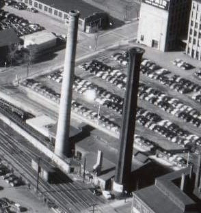
It's also visible in the 1955 Thomas Airviews aerial shots:
It took him about 15 minutes to make a rough drawing:
It turns out it's an 8-pointed star, which also means it would have been much easier to build than I originally thought. It's basically two squares, rotated within each other.
The question was what we wanted to do about the flare at the top. It's quite noticeable in the 1947 photo. All of the other photos are later, and while it seems odd that they would have removed some of it, Dick says that if it was weakening, with bricks coming loose, it wouldn't have been a big deal to strip it back a bit for safety. So we decided that the full flare was the way to go.
The next question was how big to make it. As I noted in
an earlier post, I wanted to go big because it looked more appropriate. In this case, it's a question not only of it towering over the trains, but it's quite visible towering above the building while looking down the tracks from New Britain Yard:
Jim Karl 1949
We decided to scale it down just a little bit, making it 21" instead of 24" tall. This will work better visually since I'm missing an entire city block between the yard and the stack, so it won't look too tall from that angle.
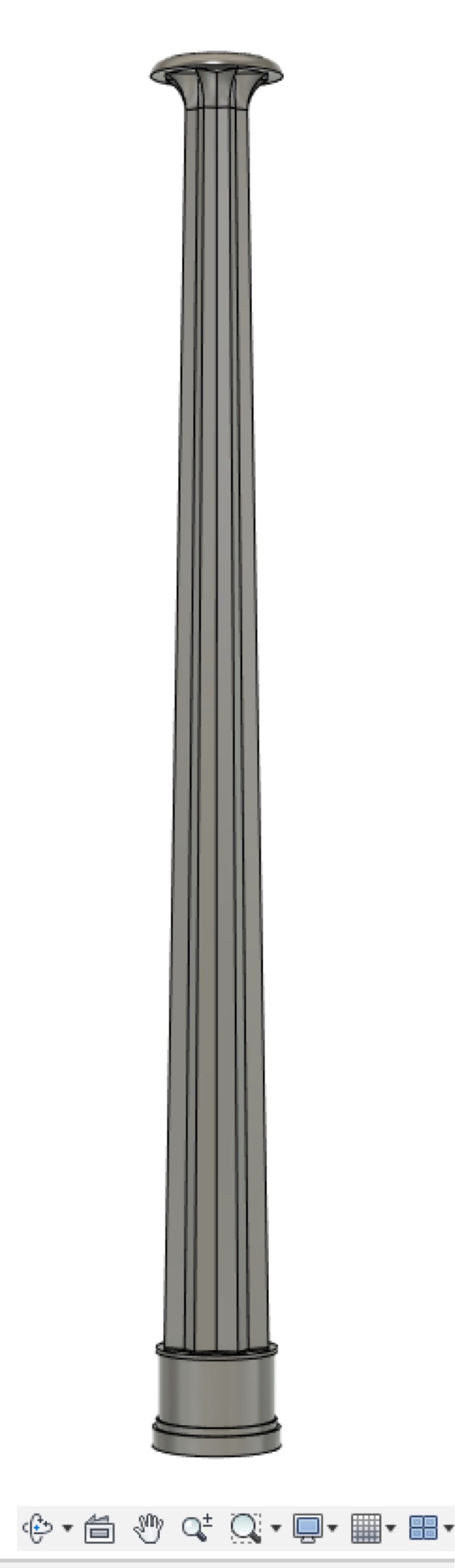
The next day he had finished the drawings. The flare, of course, was the biggest challenge. That was why he had reached out, he really wanted to take a crack at such a complex drawing, since the whole thing is tapered as well.
The next picture was the printing underway:
We decided that it would probably be better to use
N-Scale Architect brick sheet instead of trying to print it with the brick pattern. I got more pictures throughout the day...
As you can see, he had to print it in sections since it was too large for the printer to do in one pass. This was another reason why I thought the brick sheet would work well, it would help hide the seams and strengthen the joints.
I started with the curved portion, curling it tightly to take away some of the tension. Since I don't have any rubber bands, I used twine to keep it secured. I used some Liquid Fusion polyurethane glue, I also experimented with styrene cement, and found that it worked well, especially if I applied a liberal amount to the stack first.
For the stone around the base, I had some flexibile Chooch material on hand. I decided to try to thin it as much as possible using the Dremel:
I also found that I could use the Dremel to roughen up the top edge and blend it in better. Then it was a matter of cutting out pieces of brick sheet for the stack itself. Since it would require three courses of brick sheet from top to bottom, I decided it would be easier to work in halves. I glued the two lower pieces together, and the two upper pieces. Once they were sheathed, I could glue the two halves together and then finish the sheathing in the middle. This also meant that each joint was in the middle of a section of brick sheet.
The flare was tricky. I first did a couple of sections up to the top just below the flare, then worked in smaller pieces. I decided that the seam was hard to work with that way, so I then just started working with a full length piece. As it turned out, it wasn't that tough. I cut out the rough shape, held it in position to trace the curve on the the back, then cut it out. A good amount of styrene cement and finger pressure and it went pretty quickly. I tried to ensure that the last pieces would be added to the back in case I couldn't make those seams as clean.
My go to brick paint right now is a Rustoleum dark red plastic-safe primer in a spray can. I had drilled a hole in the base so I can eventually mount it over a piece of dowel mounted into the benchwork so it won't fall over. I used a piece of threaded rod and clamps to hold it while painting:
It was in the 50s, but I brought it in to dry as soon as it was sprayed. My method for applying mortar is to brush on full strength acrylic unbleached titanium white paint. This is thick, like from a tube. I then just wipe off the excess with a paper towel while it's still wet.
I then did a quick weathering with Bragdon Powders, as an initial attempt with Pan Pastels came out with a bit of a sheen. For the stone base I used my usual technique of a paint pen and stippling Pan Pastels while wet. I then used a fine brush to "paint" with Pan Pastels to provide a little more variation and highlight the seams between the stones. They look more gray in the photo (the lighting isn't great here either). In person it has more of a brownstone effect which is what I was looking for.
I'm happy with the current effect, and will see if I need to make any adjustments once I have scenery and structures.
Actually, more than happy, it's an amazing model and without Craig I wouldn't have it here at all.