Showing posts with label Wallace. Show all posts

Monday, September 6, 2021

Switcher Paint Schemes

As I've been researching the DEY-3 (Alco S-1) and DEY-5 (S-2) locomotives, I started compiling the info on paint schemes for these locomotives. 


Since there have been a few questions over the last year about the evolution of the paint schemes, I decided to create a spreadsheet with all of the paint schemes I have verified and decided to expand it to cover the life of all NH diesel switchers. A lot of the info was found in the excellent article by Marc J. Frattasio and Bill Chapin on the DEY-3 and DEY-5 switchers in Shoreliner 35.1, plus Marc's extremely thorough book on the NH, The New Haven Railroad in the McGinnis Era along with photos and official NH documents.


DEY-3 (S-1) 0967 at New Britain, December 1, 1961. J. W. Swanberg.

Through 1945, all diesel switchers wore Pullman Green with Imitation Gold Duco (not Dulux) lettering. Starting in 1946, there are no fewer than 10 paint schemes, not including minor variations, applied over about a 15 year period until the final Alpert-era scheme was first applied c1961. Road switchers carried similar, if not identical, schemes during the same periods. 


Locomotives were repainted as needed, so no locomotive wore all 10 of these schemes. It appears that most wore two to three different schemes over their lifetime.


Where known it includes the date applied. If a photo has surfaced that is within the period that a given scheme was applied, it is noted as "by (date)."


For the 401 green scheme, I have painting info up to January, 1955. I've seen a photo of 0994 in that scheme from September 1, 1955. So it had to have received the scheme between January and September of 1955. For all other schemes, the range would be from the date of adoption and the date of the photo.


Light gray cells indicate a given locomotive never wore that scheme.


Light green cells indicate that the prior paint scheme has been verified through a given period, often until the end of the NH. In most cases, the latest scheme noted was the final scheme worn. The light green shading designates those I could verify. I've included disposition dates so you can see when a locomotive was no longer in use.


I haven't dug through all of the Shoreliners, books, and other resources I have, but I will continue to update the spreadsheet as I find more info/photos. Of course, I welcome input for updates from other documentation or dated photos.


Pullman Green with Imitation Gold Duco

DEY-3 (S-1) 0967 at Wethersfield in May, 1949. John Wallace.

This was the standard diesel switcher scheme starting with the delivery of 0900 in 1931 through 1945. The cab and hood are Pullman Green and lettering Imitation Gold Duco.  The frame on most is black, but some (such as the 44-tonners) it was also Pullman Green.


There are several locomotives that appear to still be in this scheme through January, 1955, or until they were sold in the case of a few locomotives that were off the roster before that: 0607, 0613, 0803, 0804, 0805, 0806, 0808, 0941, and 0964.


Green (Pullman?) cab with Warm Orange Hood

January, 1946

Hunter Green cab with Warm Orange Hood

June 26, 1947


DERS-2b (RS-2) 0509 at Pittsfield. Sweetland.


This is the first Green and Orange scheme for switchers and road switchers. It consisted of a Hunter Green cab and 90 degree fillets at the base of the cab, with Warm Orange hoods and lettering. On the switchers, the back of the cab was also Warm Orange.


The initial scheme in 1946 does not specify the color green, but the June 26 drawing indicates the color was changed to Hunter Green. It's believed the initial color may have been Pullman Green. Only a few locomotives (0933, 0939, and 0947) have been identified to have been painted prior to the June 26 update.


In addition to the post-war DEY-3 class (0971-0995) (the first switchers delivered with the Warm Orange hoods) and the final two DEY-4 locomotives (0817-0818), the Hunter Green/Warm Orange scheme was the delivery scheme for the DERS-1b (RS-1) and DERS-2b (RS-2) locomotives as well.


Pullman Green cab with Warm Orange Hood

May 19, 1950

DEY-4 (44-tonner) 0813. Date and location unknown.

Three years later, the scheme was altered by replacing Hunter Green with Pullman Green. It is otherwise identical.


Pullman Green Cab, top of hood, and Warm Orange

June 5, 1951

DEY-4 (44-tonner) 0807. Date and location unknown.

About a year later the scheme was modified to match the delivery scheme of the second and third deliveries of the DERS-2c (RS-3) locomotives. In addition to the Pullman Green Cab, there is a band of Pullman green at the base of the hood, still with the 90 degree fillet, and the hood top is also Pullman Green. Note that there is no fillet at the top of the hood where it meets the cab. 


401 Green Hood, top of hood, and Warm Orange

May 6, 1954 (October, 1953)


DEY-5 (S-2) 0617 at Worcester engine house, May 21, 1956. Ed Ozog.

Also known as the "full balloon" or "hot dog" scheme, a 90 degree fillet is added to create a full 180 degree curve at the end of the Warm Orange in front of the cab. In addition, the green has changed to 401 Green. 

The surviving diagram of this scheme indicates that it is a correction as of May 6, 1954. Photographic evidence cross-referenced with NH documentation indicates it was first applied in October of 1953. I don't believe this scheme was ever applied to the DEY-4 (44-tonner) locomotives.

--

Onto the Matter-designed McGinnis and later schemes, well beyond my modeling era so I don't have nearly as much information for you. In particular I have far fewer photos of equipment in these schemes.

Matter/McGinnis with White Sill

DEY-1, June 15, 1955

DEY-7, January, 1956

DEY-3, May 24, 1957


DEY-3 (S-1) 0993 and 0995 at Charles St., Providence, September 14, 1957. David Sweetland.
This shows both the Red Sill and White Sill Matter/McGinnis variations.

This scheme was first used on the DEY-1 classes and was also the delivery scheme for the DEY-7 locomotives. On May 24, 1957 the diagram for the DEY-3 switchers was updated to this scheme.


It has a Red Orange cab, hood end and top, and railings, with white side sills and a white "NH" centered on the hood. The cab roof and hood were black.


Matter/McGinnis Red Orange Sill

DEY-3, -5, February 1, 1956


This design, the original one applied to DEY-3 and -5 classes, had a black hood with no Red Orange top, seen on the DEY-5 (S-2) in the photo above, It also had Red Orange cab ends, hood end, side sills, and hand rails with a large white "NH" next to the radiator shutters. 


Matter/McGinnis with Black Sill

DEY-1, -3, August 2, 1957

DEY-1b (HH660) at Boston Freight Terminal. Date and photographer unknown.


Other than the black side sills, this variation is identical to the White Sill scheme and was also only used on the DEY-1/1b/3 switchers. For the DEY-1 classes it appears that many originally had the white sills, which were then painted over with black.


Note that in the photo of 0924 above, the Red Orange is a much "redder" shade. This appears to be the case on the majority of the photos of the black sill variation. This may not have been noted on the painting & lettering diagrams because c1956/7 there was a switch the paint formulation, but both were called "Red Orange" although I don't know if the No. 406 Orange Red was used on any switchers.


New Haven Color Guide (available from NHRHTA) has a number of Red Orange color chips:

  • No. 428 Red Orange. (1955-1956) Often called "Socony Red" by modelers.
  • No. 409 Red Orange (1956-1964) Used on 1956 road switchers and locomotive repaints.
  • No. 406 Orange Red (early) (1957-c1960) Used on first 30 FL-9s and locomotive repaints.

1956 Road Switcher Scheme

March 24, 1958

DEY-4 (44-tonner) 0818. Date, location, and photographer unknown.

This is a classic scheme that is often referred to as The McGinnis scheme, It has a Red Orange cab, with everything else black, and a Red Orange "N" over a white "H" centered on the hood. Although I've never been a fan of the Matter/McGinnis schemes, this one is very clean. I like it. Although not so much on the 44-tonner. I think maybe it's because the hoods are so short. 


Apparently the handful of switchers that received the scheme was because some of these locomotives were used on local freights.


I have seen a number of models in this scheme with a black cab roof, but haven't located a prototype photo that verifies that was a variation.


Alpert Scheme

Date Adopted Unknown (c1961)

DEY-3 (S-1) 0988, date location and photographer unknown.

Sort of a reverse of the "Road Switcher" scheme, and a variation on the old green and orange schemes. It has a Red Orange hood and black cab, frame, and railings. A white "NH" is on the side of the cab instead of the hood. This would be the final scheme developed, but used on few switchers. Although commonly known as the "Alpert" scheme, it is a revision of the design developed for the RS-1 by Herbert Matter in summer 1955. 


Hybrid/Variant Schemes

Various dates


This column indicates that a given locomotive was known to wear a minor variation of an existing scheme, or a hybrid scheme. 


Variant Schemes

A variant scheme is one that has minor differences from the standard scheme of the era. For example, two locomotives were painted with variations of the original Matter/McGinnis scheme. 0963 had black side-sills, and a Red Orange cab. 0964 was painted the same way, but with 3/4 size "NH" with the "N" in Red Orange and the "H" in white.


DEY-3 locomotives 0935, 0966, and 0967 had small "NH" logos lettered on the front of the hood in one or more of their paint schemes. DEY-4 0811 had an unusual variation of the Road Switcher Scheme where the large "NH" was on both sides of one of the hoods, which meant it was to the right of the cab on one side, and the left of the cab on the other, just like the end-cab switchers or road switchers. 


Hybrid Schemes

Hybrid schemes came about because a number of locomotives were condemned but not scrapped and used for parts. In addition, at least two locomotives have been documented (0607 and 0975) were only partially repainted during the Alpert era.


There's an interesting thread on the NHRHTA Forum that initially looks at S-1s, but there are other locomotives pictured as well, mostly in hybrid schemes.


These practices had the effect of creating a few unusual schemes that were hybrids of a cab from one era and hood from another. 0603 had an early McGinnis black hood with a Red Orange end, along with a black cab. Likewise, 0993 had an early McGinnis hood, but a Green cab with the script herald. There may have been others.


Heavy Weathering and Paint Failure

In addition, if you're modeling the '60s, the weathering was substantial on switchers that had not been repainted in years. Photos are your best bet for this era, because the paint was wearing thin, often revealing older schemes beneath the current coat, or even wearing to the gray primer. Lettering, even including road numbers on the front of the hood, sometimes wore away. I didn't note heavily weathered locomotives in this column, even with old paint schemes showing through, as they are not hybrid or variant paint schemes. But the light green shading indicates a locomotive that was still wearing the last noted scheme in a given era. Those that are older will be more heavily weathered and you should search out photos.

Friday, September 3, 2021

Power for the New Hartford Local

Chris has gotten started on building his undecorated Proto 2000 S-1 for a New Haven DEY-3 class switcher. I had started some modifications on mine a while ago, and we need to add decoders as well. So naturally, I pulled mine out to provide some input. Which has led to the locomotives hitting the bench for some more work.

So what locomotives will I need? 

In my case, I need the S-1 for the New Hartford Local. Although I usually refer to this as HDX-5, it's a bit more complicated than that as things were changing throughout the era I model. For now I've decided to focus on 1949 and later since it will be easier to get the diesels running. Especially since HDX-5 used a K-1-d mogul with Southern valve gear, a variation that NERS never released (despite the initial announcement that they would). So until I'm comfortable I have the skills to modify the valve gear on a brass model I'll start with these.

1949

HDX-5 was briefly eliminated in early 1949 when the K-1-d was pulled, and the tonnage absorbed into NY-4 which would work the New Hartford branch on Monday, Wednesday and Friday.

Presumably there was enough traffic, perhaps combined with the fact that HDX-5 originated in Hartford instead of Cedar Hill, and it was reinstated by September, 1949 with DEY-3 (S-1) no. 0967 assigned. It was built on May 13, 1944. 

John Wallace took this photo of  0967 on the Valley Local in Wethersfield in May, 1949. 

John's photo shows that the locomotive was still in it's delivery scheme in early 1949, and records confirm it wasn't repainted until April 3, 1952. So for my purposes it's still Pullman Green.

In 1952 it would have received the current (as of May 9, 1950) scheme of a Pullman Green cab and hood top, with a narrow band of Pullman Green and the curved fillet at the base of the hood, and the remainder of the hood in Warm Orange. This was the third scheme that the DEY-3 and DEY-5 (S-2) locomotives wore.

Later on, it was one of a few of S-1s that received the August 2, 1957-March 24, 1958 Matter/McGinnis scheme with black sides on the walkway. It was one of a few that had a small "NH" on the front of the hood. I haven't identified any other schemes worn by this locomotive, so the third scheme it wore may have been its final one. It survived to the Penn Central era.

1950-1951

In autumn of 1950, the assignment for HDX-5 has changed to DEY-3 0994. This is one of the postwar S-1s, the second to last one, and was delivered in Hunter Green and Warm Orange on January 1, 1949. 

Chris found this undated photo of 0994 in Wethersfield. Looking closely, you can see the line between the green hood top and Warm Orange hood. The question is, which green?

In mid-'51 the NH started the Pullman Green/Warm Orange scheme that 0967 received in 1952. But in a document dated January 27, 1955, no. 0994 hadn't been repainted yet. At that time, the current scheme was 401 Green with Warm Orange, and a 90 degree fillet had been added at the top next to the cab. In other words, the "full balloon" or "hot dog" scheme. This scheme was replaced by the first Matter/McGinnis scheme on February 1, 1956. So it must have been the "full balloon" scheme.

Sure enough, here's a photo confirming this scheme:


Location, date, and photographer unknown.

This was the fourth scheme worn by these classes. I haven't found any record or photo showing that 0994 was subsequently repainted prior to the PC era either. There are some photos of DEY- class locomotives in these (very worn) schemes in the late-'60s so it's possible that neither 0967 or 0994 were repainted again.

I don't have any engine assignments for 1951 so for now I will keep 0994 on that assignment.

1952

In Spring of 1952 the New Hartford local and the Cedar Hill-Holyoke local were combined, operating out of Hartford. By September 1952 the New Hartford local is reinstated, now as NX-25 after the elimination of the Hartford Division. It still originates in Hartford, and has DERS-2b (RS-2) 0503 assigned. This is convenient, since it's one of the two locomotives regularly assigned to NY-4/YN-3 in earlier years and I've already modeled it.

I don't have any repaint information for 0503, but here's a shot in South Boston in another scheme:


Date and photographer unknown.

This scheme, the same as noted for 0967, was applied from ~June, 1951 to ~June, 1953,  and was the second scheme applied to RS-2s.

The diagram for the following "full balloon" scheme was dated for June, 1954, but it was noted as a correction, and photos indicate that the switch occurred earlier, probably mid-1953. So there's a possibility that 0503 would have the pictured scheme by late '52, but it could have been sometime in 1953 as well.

1953

In fall of 1953, NX-25 and NY-4/YN-3 are replaced by NX-28, but it now operated out of Plainville. 

No 0967 is assigned to this train, but we know that 0967 was repainted in the above scheme on April 3, 1952 as noted above. But it doesn't work New Britain at all, which is one of the reasons there are no daytime freights in my November, 1953 ops sessions. This train, as NX-28, would switch back to originating in Hartford for fall of '54 and NY-4/YN-3 would also be reinstated by then. Tom McNamara caught DERS-3 (Fairbanks Morse H16-44) no. 590 on the job in that era.

All of these changes are beyond the operating sessions on the layout. 

Repaints?

During this era, locomotive paint schemes were changing frequently, and those schemes help set the era. But not all of a given class received a particular scheme. Although I know 0967 was repainted by 1953, it doesn't look like it was operating in New Britain at that time.

As for 0503, that could have been repainted after November, 1952, the last year it will be running on the layout. At that time, there are a couple of DERS-2c (RS-3) locomotives, one of which will be in that scheme (and the other in one similar to the RS-2 delivery scheme, but Pullman Green and including a band of green along the bottom). So three different RS- paint schemes running at once if I stick with the delivery scheme on 0503. I do have a third model already disassembled, and I could do a second model if I wanted to. For the moment that will stay on the back burner unless/until I find documentation that it was repainted prior to November, 1952, and I'll get working on the S-1s instead.

Friday, October 26, 2018

Scale Track Part III

As I mentioned, Chris needs a scale track for his layout. While the Blair Line model I used is a nice kit, the main thing I didn't like is that the floor is a thick piece of wood that ends up flush with the sides. While you can (and I did) paint and weather it to look like a concrete slab, if it's a foundation it should be inset a little bit. In addition, based on measurements found online, I think that the board-and-batten siding uses oversized boards. Overall, I also prefer working with styrene than wood.

But really, I figured it's a simple little building to try my hand at scratchbuilding.

After going through the Railway Prototype Cyclopedia article, I realized I had missed that there is a 2-foot clearance around the scale itself, including the ends, within the scale pit. Which means there is at least 2-feet of wood boards between the end of the scale and the end of the scale pit. It also allowed me to ensure my measurement on all sides were within the standard.

So I started by taking rough measurements of the completed Scale House and cutting out the basic parts.


The basic parts and their scale dimensions.


Then I plotted out the windows and the door. Since the windows will have a frame, cutting out the side windows right to the corner won't be a problem. The same thing in cutting the front window from the top.


Board and batten siding can be made from a lot of different size lumber. But the dimensions I went with is essentially a 1" x 10" main board, with a 1" x 4" batten. The space between the battens works out to about 8" so I drew lines at 1' intervals.


I decided on the dimension in part because of what I thought looked good with the options I had on hand, and also what closely matched the dimensions noted on construction sites online.


So I marked the lines on all the parts, and started cutting out the windows and doors. I then completed the battens on a couple of pieces to see how I liked it.


You'll note that the side of the building has been redrawn with a new window location.


And the door has been moved to the back. Why? Because I wasn't really trying to recreate the Blair Line model. I want to make the structure that was there. Of course, we only have a (very) partial shot of the scale house in Middletown.  Here's John Wallace's photo again:


I've decided that since most scale houses had windows on both sides, and I think a door would be taller, that the frame on the side is a window. It's pretty much centered on the side, so I moved the windows on both sides. Which means the door needs to be moved to the back. So part of me says the door would be on the side, so you're never stepping out of the building into the way of a moving train. But the general need for the windows makes a door on the back logical.


The other New Haven scale house picture that I could quickly put my hands on is this one. I've seen others, and I can say every once is a little different. Some had the angled corners like the Walthers model, and others were this simple rectangular shack. Since this looks quite similar to the one in Middletown, I'm using it as a guide as well.

Of course, the other factor is that this one has horizontal side sheathing, and looking at the Middletown photo it looks like vertical boards but no battens. Since it's for Chris' layout, I figured I'd see what his preference is. Both of us agree that's what we think it looks like. So here are the pieces cut out of some scribed wood I had on hand.

Note that on the styrene version I decided to cut the large window opening lower, and the piece I cut out has been moved up to frame the top of the window.

The styrene parts make a nice template, and I may decide to complete that structure eventually. But for now I'm working on the wood one.

So it seems as good a place as any for a few comments on materials. I like the idea of using wood because you can stain it and sand it to weather it like I did on the deck of the first scale track. Stain doesn't penetrate styrene, and sanding styrene after you've painted and weathered it just exposes white styrene. So there are some interesting finishing and weathering approaches with wood that you can't do in styrene. In addition, cutting out windows in wood is much easier, as it's a softer material than styrene. However, wood has a grain that styrene lacks. Cutting across the grain is much different than cutting with it, and in most cases when cutting against it I found a razor saw a better tool when I could use it.

Styrene, on the other hand, is easy to cut with the score and snap method, but that can't be used for the first three sides of a window. I also find that when trying to cut all the way through styrene (instead of score and snap), even with multiple passes, the result is an edge that requires filing to finish because it's not perfectly straight. But the biggest benefits is that it doesn't warp like wood, especially thin wood. Paint and glues have more than enough moisture to make these significant issues. Thin styrene is stronger as well. Furthermore, gluing styrene is both simple and strong with styrene cement that "welds" the parts together. While the old adage is that when gluing two pieces of wood together, the joint is stronger than the wood is true. The problem is, the wood we typically use in modeling is very soft. So a layer of wood can easily slough off with the glue.


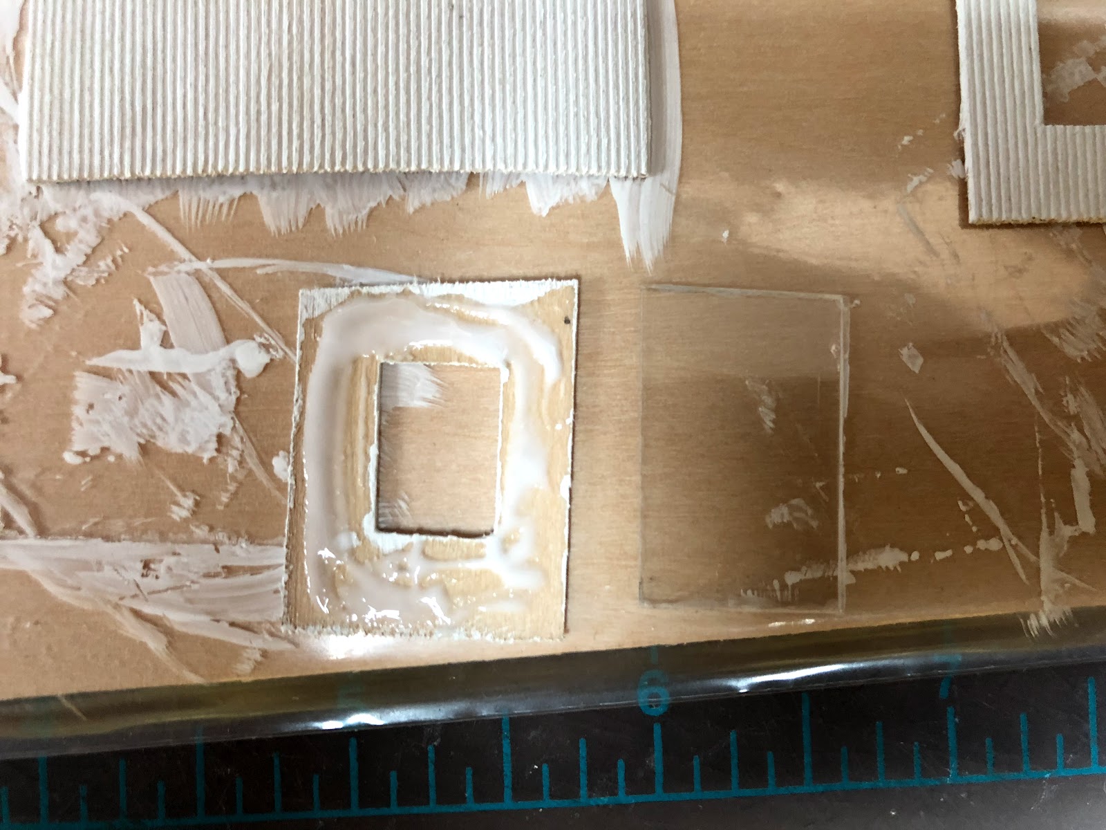
So you'll note that after painting with a craft acrylic, the wood has warped considerably. Especially the pieces with a window or door cut out. I knew this would happen (and that this wood was too think for structural integrity anyway), but I didn't want to strengthen it until after painting...


So I could use clear styrene for both structural strength and as window glazing.


Since I hadn't determined exactly how I was going to assemble the model, I cut the styrene so it was smaller on all 4 dimensions. This allowed more flexibility in assembly.


I used large 8' x 8' pieces to act as both a frame to assemble it, and the foundation of the building. 


Because the primary interior structure is the clear styrene, all of the window glazing is done. I chopped up some old Walthers windows (what I had on hand), but decided they were too coarse for the model. So I have several other options on order and I'll decide which I like best. I'll be able to paint them before installation so I don't have to worry about harming the glazing.


I haven't finished the roof, obviously. The door is scratchbuilt. The interior on the back is regular white styrene since there's no window. I first drew the pattern on the door and started by installing the first horizontal piece at the top of the door, then using a full piece of strip styrene one of the vertical pieces (the long "handle" makes it easy). Once the glue had done it's job, I cut it to length (to where the next horizontal piece is), and did the same for the other two verticals. Then I added the horizontal piece, and used the same approach for the bottom half of the door. I drilled a small hole and used a piece of wire for the door knob.

I also used strip styrene to finish the corners and fascia and the frame around the door. I will do the same around the windows once I've installed mullions.

Next: The next major piece was the scale track itself. Unlike New Britain, it's a gantlet track in Middletown. Something I had wanted to try.

Friday, October 12, 2018

Scale Track

So I decided to plan ahead and build the scale track before I permanently install the Whiting Street Yard tracks. Shocking, I know.

In my case, it's a relatively easy track to make. Since it's a stub-ended track dedicated to the scale, I'm assuming there's no gantlet track. I don't actually have any pictures of the scale track, but my research indicates that (in 1915 anyway) it was a 42-foot, 100-ton scale. I don't actually recall where I dug up that information, nor do I know if it was upgraded to a higher capacity.

We do have a picture of the scale track in Middletown, thanks to John Wallace. I don't know think he intended to get the scale track in the shot, but we've got it. This was (in 1915) a 34-foot 50-ton scale, and again I'm not sure it was ever upgraded. Nor am I aware if it was still in use in 1947. But it looks like it's in good shape in this 1947 photo, although the tracks beyond it don't look like they are well maintained.

If it was, I would guess it would have to have been upgraded above that capacity. We do have a track plan dated May 27, 1959 indicating the track is to be removed.

My guess is that the track scale here was used much like the one in New Britain. In New Britain, I'm convinced that the most use would come from shipments of trap rock from Lane's and Cook's Quarries. Perhaps there's some coke being shipped from New Britain Gas Light Co. In Middletown, there were brownstone quarries across the river in Portland, or just beyond. A 50-ton scale would be insufficient in 1947, and 100-ton barely so. I wouldn't be surprised if both had been upgraded by then.


In this case, you can see that it has a gantlet track, because it was built as a double-ended track, unlike the one in New Britain. Looking at the picture, the rails run along the top of the scale beams, and there are small metal rain shields that keep most of the rain out of the scale pit. between and outside the rails is wood decking that is at the same level that ties would be.

--

For a quick overview of track scales, they were situated at various yards on every railroad. Major yards would have one, and sometimes smaller yards, as is the case with New Britain and Middletown. L.C.L cars were not weighed, since the goods were weighed before loading. Regular loads from an industry, such as Stanley Works, were probably not weighed either. Instead, standard weights would be predetermined for their goods, such as a case of hammers. Bulk goods, on the other hand, such as coal, coke, or stone, would need to be weighed. Cars loaded at the bulk tracks would probably need to be weighed too. They would be weighed at the first scale en route to their destination.

The scale itself is housed in a concrete pit, with the rails (or one set of them if there's a gantlet track), running across the scale bridge itself. This is connected to a scale that is inside the scale house, and the operator uses weights and a slide, much like the old doctor scales, to determine the car's weight. They could do this very rapidly, even weighing cars in motion on some scales. Periodically, a scale test car with a known weight would be used to calibrate the scale.

The pit is covered by wood planking, and there are rain guards along the rail to prevent too much water from getting into the pit.

Railway Prototype Cyclopedia Vol. 12 has an excellent article about weighing freight cars and track scales.

Operationally, in my case YN-3 will drop of hoppers of stone to be weighed and then blocked for YN-1. For some sessions, the scale test car will be brought in and the scale calibrated.

--

I didn't want to just put wood planking on top of the ties on the track, it should be lower than that since there are no ties used. But how do I keep the track in gauge across that distance? Well, it's going to be similar to how I keep the track fixed and in gauge at the edge of the liftouts.

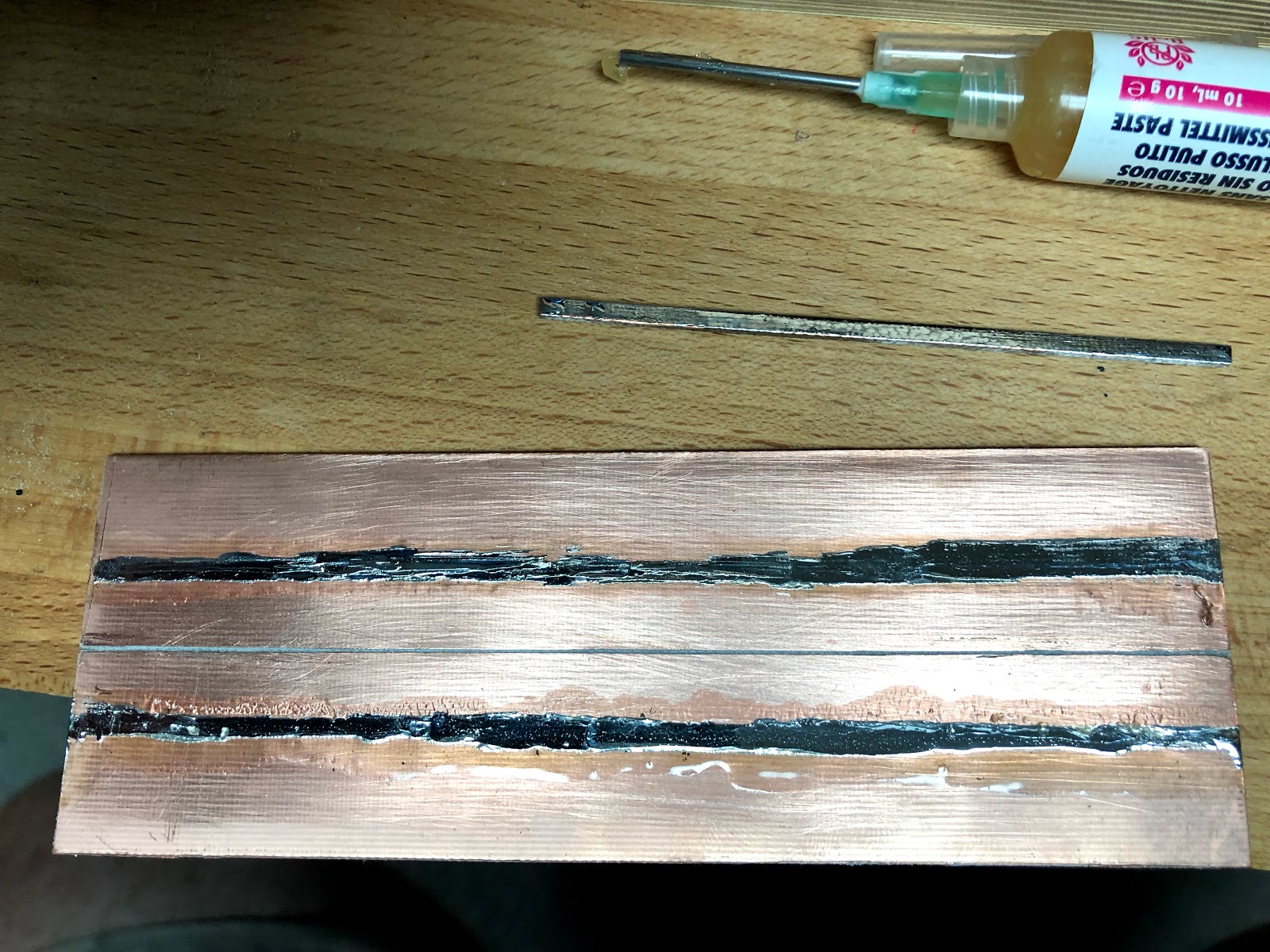
I started with cutting a 2" x about 6" piece of PC board. This is laminated with copper on only one side instead of both, but that's all I need. It's a very tough material to cut. The guy at the shop told me to just score and snap it, but that wasn't working for me, and I was afraid it would splinter. I took it to Chris to show him and get his opinion, and he just snapped it. I'm still having trouble snapping it, but I've found that if I score it on both sides and use pliers, I can get it to snap. I also found that after I get the score started (and all the way through the copper) with a utility knife, that a razor saw works better to get the cut deep enough.

The PC board is a sub-base that will have PC board ties soldered on top, and the rail will be soldered to those. For the lift out, these ties will replace the plastic ties. In this case, though, in addition to replacing the plastic ties, they will run parallel under the rail, instead of perpendicular as railroad ties. This is what will maintain the gauge through the scale track.

Note that on my layout, I have a thin layer of craft foam that covers the entire deck. When I first started laying track - in the helix no less - I used N-scale cork to reduce the noise in the helix. I continued that onto the main deck, since the roadbed in New Britain is pretty flat. As it turns out, I probably shouldn't have used roadbed at all. So I needed to fill the spaces around the track to bring the ground up, and started using the craft foam.

When building Whiting Street, instead of using cork at all, I decided to just use the foam for the entire deck. It works well, and I think will help reduce noise. 

It's important in regards to this project, because it's the same thickness as the PC Board, and I'll cut out the foam where the scale track will go. As long as you're using roadbed for your track, this will work, although you might need an additional layer of material under the PC Board to bring it up to the correct height.


Here's the PC Board 


Here's the JMD Plastics rail alignment guide with the PC board ties mocked up. The alignment guide has convenient holes (for nailing track down) that allow me to see the gap I filed and align everything. Fast Tracks makes a similar alignment guide.


It's not pretty, but here are the two rail lines tinned. I'm using a no-clean flux, something I recommend every model railroader has because I'm finding that for some of my feeders the solder joint and plastic ties have been eaten away by flux that wasn't fully cleaned.  


It's hard to solder and take pictures at the same time!
Tinning the ties is a challenge. I found I could put flux on the length of the tie, put a blob of solder at one end, and use a small file as a stop. I could hold the file in place, and smooth the solder down the length of the tie without burning my fingers. This approach of smoothing the solder also worked on the larger board.

I had some scraps of scribed wood, and used that as the deck. It needed two layers, and for now the top layer is wider and longer since it should be 2" x 6" decking, not 4" x "6". Most likely this will be cut back when I build the concrete edging that surrounds the pit.


You can also see a test piece of track with the ties removed. I found that the PC board ties are right along the inside edge of the rail base. It will work fine, but if I were to do it again I'd move the PC board ties in slightly to better center it beneath the rail.

Normally I'd probably try using the Proto:87 Stores etched tie plates. But since they would be hidden by the rain guards I don't need to worry about them here. I'll use a similar approach to build the engine servicing pits and will try them there.


After gluing the decking with the usual Aileen's Tacky Glue, I turned it upside down and weighted it with a power driver.