Showing posts with label DEY-3. Show all posts

Monday, June 24, 2024

NH DEY-3 Part IV: Painting

During the tail end of recovering from Covid I decided an easy thing to work on would be some painting. Getting out the airbrush is one of those things that seems much more complicated than it really is. Especially since I've set things up to be as quick as possible, both getting started and getting cleaned up. I've done a few posts on the DEY-3 project before:

Part I: Installing DCC  - Part II: Details - Part III: More Details

Some time ago I painted body and cab for what will be 0967, then installed the windows and it's ready for next steps. This was an easy job since it's all Pullman Green. I used Stynylrez gray primer and Badger New Haven Pullman Green.


Incidentally, 0967 also ran on the Valley Line for a while, and Chris has done an extensive series of how he modeled this locomotive. His progress is part of what got me looking at my models again. There's little point in me describing the same steps that he took for his excellent model. Here are his posts:

Now that Chris has so thoughtfully asked (assigned) me to be editor of Speed Witch, I expect a draft of this article soon...

The second unit, 0994, was delivered in Hunter Green and Warm Orange. I had started this some time ago, but wasn't quite getting an orange that I liked. The Badger New Haven Warm Orange looks right, but over the gray primer it looked dingy.  So I tried it over Stynylrez white primer, and then it was too bright.


Then I found out Stynylrez has an orange primer (they also have a dark green). That's what I used this time, and the Badger looked good over it, but still not quite the correct orange. Orange paints are fairly transparent, and it takes several coats to get to the actual color that it appears with a full coat. I decided to take advantage of this effect and try what is often called a "filter."  This is using a thin coat of paint over the existing color in order to alter it. In this case, Vallejo Air orange had a bit more red (I think) in it. It doesn't look right by itself, but I thought that it would shift the Badger orange just enough.  After a couple of thin coats of the Vallejo orange, I compared it to the NH Color Guide paint chip:


It's not a perfect match, but I'm very happy with how close it is. It's also repeatable, and that's what I did for the back of the cab - Stynylrez orange primer, Badger NH Warm Orange, and Vallejo Air orange in that order. The green is Stynylrex green primer with Badger NH Hunter Green. Here it is next to the Pullman Green 0967. The back of the cab looks like it has a bit more red in this photo, but that appears to be a combination of the lighting, angle, and how the camera picks it up since it doesn't look that way in person. 


I also compared it to the Life-Like factory colors on the RS-2. Again, close enough for me.  Mike Redden included pre-cut masks for the fillet with the low-profile cab kits, so I masked it up and added that. Here are the with windows, crew and interior. 


I plan on a gloss coat, probably of Future (I have some left) or Quick Shine (a different brand of what seems identical).  Part of the reason is that these products can also be used to eliminate scratches and clarify clear parts. So I won't need to mask the windows (just cover up the engineer behind the open one).  Once the lettering is done, I will do a semi-gloss finish since these are relatively new locomotives on my layout. Then weathering.

Wednesday, July 26, 2023

NH DEY-3 (ALCo S-1) Part III: Shutter Control and Water Fill

Continuing with the DEY-3 models. Units 0971 and later were delivered with automatic shutter controls, while the earlier units had manual shutter controls. The Proto 2000 model comes with parts for the manual shutter controls. It's a small plastic part that mounts near the fan housing, and a long pipe that goes to the cab. There are starter holes inside the hood to drill out for this part. I didn't have a drill bit long enough so Chris drilled them out for me.


The Precision Scale no. 3321 Hancock vertical check valve looked like a decent match to the small motor mounted on the fan housing with the automatic shutter control. On many roads there's a small rectangular box, which is simply protecting this motor. It would have been easier to model.


To start, I drilled a hole at an angle where I wanted to mount it. I also cut off the small round extension on one end and filed it flat, and filed away the mounting bracket that is around the post. I've been using these tungsten bits a lot and find that the large diameter shaft works well as a handle and often just use them manually like this.


While working on this part, I also drilled and cut out the plastic around the fan so it will be open for the speaker. Once I mounted the part, I soldered one strand from a 32 AWG stranded wire as the conduit.


I drilled the hole for the other end based on a photo.


Many earlier units received automatic shutters as well. This motor is on all of them. Some of them received the new radiator shutters, while others retained the original shutters when converted. Not all of the S-1s received the automatic shutter systems, so I'd recommend modeling from photos.

There's also a small water fill pipe missing on the model. I made one by using a piece of 1/64" styrene rod and gluing a piece of 0.035" styrene rod centered on the end.


I cut the larger rod to a thickness that looked good, then glued a second piece of the smaller rod on the other end.


I drilled a hole in the model on the center line roughly halfway between the fan housing and the first panel seam to insert the part.


Then I trimmed off the top and filed it until I liked the dimension.


I also decided I'd rather glue on the fan shutters before painting, so I removed the fan altogether so I wouldn't have to worry about how to mask that. I'll install it after the unit is painted. I also need to figure out what to use for the fan for the other unit, since it started with the round fan housing and I drilled that one out.


Here's how the shutters and shutter actuation systems look on the two units. They've been primed with Badger Stynylrez primer, which I am finding that I love. It's very easy to work with, and appears to be a perfect base coat.

Wednesday, July 19, 2023

NH DEY-3 (ALCo S-1) Part II: Shutters and Whistle

It's been a while since I've been working on the DEY-3 (S-1) locomotives, but Mike Redden brought the new one-piece cabs he's 3D printing at home, instead of the flat kit he has available at Shapeways. In addition he now has the proper fan shutters and the low-profile radiator shutters.

I'm working on two units for HDX-5, nos. 0967 and 0994 for different years.

There are two versions of the Proto 2000 S-1, here's the one with the square fan housing. It comes with an etched fan grate, but unfortunately it should be shutters like an RS-1. Also note the radiator shutters, with 11 wide shutters and how they protrude a couple of inches from the hood. This was a later style of shutters, automatically operated. On the New Haven, this style was on the post-war DEY-3 locomotives, starting with no. 0971.


Chris started a chat with our CAD buddies Chris Zygmunt and Mike Redden last year to produce the correct cooling fan shutters. Mike has them available now, designed to fit the Proto 2000 models. I was able to provide photos and measurements from an RS-1 shutter, which are identical.

I'm not using a walk-over grate. Based on photos, it appears that the New Haven didn't install these until c1954 with the introduction of the "full balloon" paint scheme. Although there are a few photos in other schemes with them, all of the dated ones are 1954 or later.

One photo of 0943 in Hartford has the narrow walk-over grate and it's still in the Pullman Green delivery scheme. Its next documented repaint was April, 1954 in the "full balloon" scheme, and was obviously prior to 1943. But I haven't documented any others, and also not with the narrow grate. 


It's a see-through part with the shutters partially open, which is great because I've mounted the speaker up front. This is mounted on the second version of the Proto model. I drilled out the top and scratch built the square housing to the same dimensions as the other model. Why? Because that version of the model has flush-mounted radiator shutters. Unfortunately, it still has the 11 wide shutters, instead of the 24 narrow shutters on the prototype. Now that Mike has made the correct ones, I'll replace them.


To do that I just drilled a bunch of holes, then cut and filed away the old shutters so I could replace them with the new ones. Mike's part installs from the outside, and the flange covers hides the seam, so it doesn't have to be perfect. Here are a couple of pictures with the new fan and radiator shutters. This will be no. 0967.


Here's a shot of Mike's one-piece cab with the low-profile New Haven roof. I've also shortened the stack to the same height. The bell has been removed (it's mounted under the frame) and the New Haven used a 3-chime whistle instead of a horn.


I'm using a Custom Finishing no. 103 whistle, as it's based on the NH prototypes. It's slightly large/tall, but their shorter whistle is based on a NYC single chime prototype. I'm also using one of the pipes with an elbow from the Precision Scale no. 4839. It's marketed as O-scale parts, but will work well for this. The Precision Scale no. 3321 Hancock vertical check valve (a part that's no longer produced) will be used in the next post...


The pipe has an elbow that is already cored. I shortened the post on the whistle and soldered them together.


Although probably large, I used a strip of 1"x8" styrene because it was wide enough to drill for a Cal Scale no. 512 U-bolt to attach the whistle in the same way the New Haven did.


I scored a second piece of 1"x 8" styrene so I could bend it to make a handle for the other part of the whistle bracket.


You can see how I'm installing it here using styrene cement, and a picture of the prototype behind it. On no. 0967 it's mounted about a foot forward of the cab roof.


On the second unit, no. 0994, it is mounted about three feet forward. you can see the difference in spacing between the two below:


More to come...


Friday, October 22, 2021

NH DEY-3 (S-1) Railings

The railings on the Proto 2000 models are very fine, and appear to be to scale. So why would I want go through the trouble of replacing them with etched parts? 

This crop of 0937 taken by Ed Ozog shows the end railing matches that of the Proto 2000 model. The lower portion of the railing curves back up and attaches to the pilot above the uncoupling levers.

This arrangement was only used on the first 10 (0931-0940) New Haven DEY-3 locomotives.

On the remaining locomotives, the railing continues straight, with a right angle turn to attach to the pilot just above the step. This is visible on this crop of 0994, photographer unknown.


Otherwise, the rest of the arrangement appears the same.

So that leads me to checking out the etched parts as an alternative. But they are slightly larger stanchions than the P2k ones. In addition, they have the additional detail of the two rivets on either side of the stanchions (not just the ones that attach the stanchions to the frame). Plus, I just like trying different things and expanding my skillset.

Friday, September 24, 2021

Fun with 3D Printing

I recently pointed out to Chris that the etched grate that is on the Proto 2000 S-1 model is incorrect. The S-1, as with the S-2 and RS-1 locomotives, had shutters over the fan housing, not a grate. The New Haven and many other roads later installed a walk-over grates, but the fan itself was covered by shutters.

Chris had the good sense to start a Facebook chat with our buddy Mike Redden and another one of our 3D printing buddies, Chris Zygmunt.


Within less than 24 hours, we had photos of multiple test prints to discuss as Chris Z. and Mike had worked up several variations.

Chris Z. printed out several and left them with Chris A. and last night I picked them up while at Chris A's for an ops session (yes, I know a whole alphabet's worth of Chris-es)...

The discussion revolved around a number of things, one of which is how it will be installed. The P2k model has a slight lip on the inside of the fan housing to hold the etched part. So a logical approach would be to be a part that can just drop in.

However, the actual set of shutters rests on top of a slightly larger housing. By making it the size of that frame, one can simply sand off the old frame (leaving the larger housing) and glue this on top. Another advantage with this approach is that the same part can also be used for the Atlas RS-1 and S-2, since those don't have an etched part to replace.

I have cut out the fan in my models, because I'm hoping to let the sound come out through the fan housing. To this end, I'd like a set of shutters that has openings between them. 


So the first one I tried of the three that Chris Z. printed has 16 shutters, with spaces between them. The shutters of all of these are at a 45-degree angle, but are so small I'm not sure that will be visible. Only about 1/3 of the slits were open, so I cleaned the rest out with a scalpel.


I did end up with two small cracks in the process, but didn't look problematic. Until I was trying to cut off what was left of the supports and broke the end off altogether.


It won't be a real issue, though, it fits together cleanly. So here it is just placed on top of the shell.


I really like it, I'll see what the others look like. This is the one with the full 22 shutters that I believe is prototypical. It's slightly too small, but it really looks correct otherwise. I tried to open up spaces between the shutters but there isn't any way that will work.


The third option has 20 shutters, and is sized to be an exact replacement for the etched part, so it drops right in. Again, I couldn't open up spaces between the shutters.


I've seen photos of Mike's versions, but don't have any in person yet to check out. I may very well use a couple of different ones. Looking forward to those (as well as the radiator shutters Mike is working on).

I'm glad Chris had the foresight to pull the group together, and Chris Z. and Mike continue to impress me with their skill in creating parts like these. I'm torn on whether I like the 22-shutter or open shutter version better. Let me know what you think.

Wednesday, September 8, 2021

Proto S-1 - Installing DCC/Sound

For the DEY-3 (S-1) locomotives, I'm using the Proto 2000 model. Mine are the pre-Walthers, my understanding is that Walthers made some modifications to the drive/chassis with a shorter motor, which would alter the process I used slightly.

The models themselves need very little in the way of detail alterations, with the biggest one being the cab. One of my shells (well, three of them, I have two spares) are at Chris' but Mike Redden is finalizing a new set of radiator louvres for the earlier version of the locomotive. So I'll cover all that in detail in the future.

After a couple of evenings of experimenting and testing, it took me an evening to do each one. I don't rush, and do a lot of test fitting and tweaking. I also ended up completely disassembling it to the frame so I could properly clean the trucks and to keep bits of metal from getting into the gear boxes while modifying the weight and frame.

For soldering, flux then tin each wire, and flux both wires before soldering them together. If everything is tinned and fluxed it goes very quickly and cleanly. I use a no-acid no-clean flux. Don't forget to thread a bit of the shrink tubing on first.

I wanted to use Scale Sound Systems' speakers in these (and future) locomotives. They appear to be 3D printed enclosures and have the speaker preinstalled. Most importantly, it is designed to fit a specific model by an audio engineer. His instructions specifically note that you should not modify the enclosure to make it fit. Of course, that means I did. I don't think these are problematic, but YMMV.


The instructions JT provides has you remove the weight altogether, and install the speaker using screws that used to hold the weight in place. There's a gap under the speaker on mine, and I suspect that's due to this being the older chassis. It's unclear in the pictures on the site whether a spacer was used under the front.

But I wanted to keep as much of the weight as I could as well, since these will have to haul the New Hartford Local up the helix. Out comes the Dremel.


I cut it just beyond the portion that covers each flywheel.


I had to cut off one of the mounting lugs on the speaker as well.


This allows it to sit in the same location, but retains 2/3 of the weight.


Of course, it no longer screws in on the left. I had to modify the lug on the right because it extended too far, and then extend the hole to the edge of the enclosure itself. It still doesn't screw straight into the existing hole. However, with Kapton tape to hold the speaker in place, I decided the screw wasn't needed.

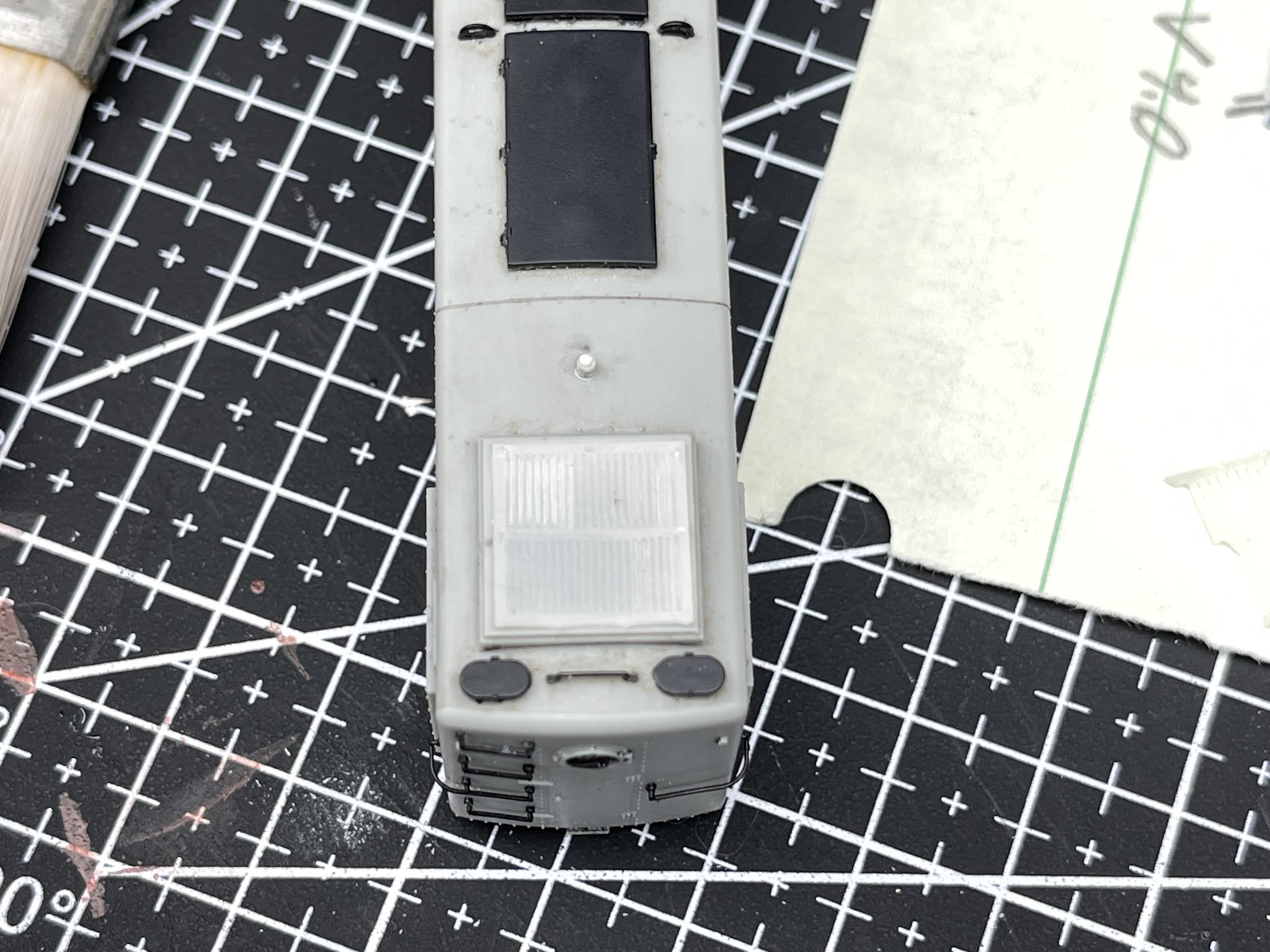
I frequently test-fit the shell to make sure everything was low enough.


An ESU Micro conveniently fits in the cut-out for the motor connection:


And an ESU Power Pack fits in front of the cab as well:


One issue with the Proto S-1 is that motor is electrically connected to the frame. Note that this doesn't prevent you from installing DCC, it's a similar design to a brass steam locomotive. However, a problem can arise is the wheels of the opposite polarity accidentally touch the frame (which can happen in a derailment). That short can fry the decoder. So I decided to go ahead and isolate the motor electrically from the frame. First by using Kapton tape:


You can see the nut on the bottom of the motor above. That's usually in contact with the frame. Fortunately, they also provided a copper tab for soldering a wire to it. The fit is very tight, so I soldered the wire to the side of that tab:


Then tested:


For the second one, I decided to cut away a portion of the frame here, to give it more room.


The Kapton tape was working fine, but after installing/removing the motor several times I noticed I had torn it on the second chassis. It doesn't appear that I did so on the first one. But this ensures that it has enough space and won't happen again.

The next challenge was the wiring. The old wiring went through holes in the weight, which is now covered by the speaker. Instead, I taped the wires from the front truck along the chassis. You'll see that there is a flat spot on the chassis just next to each flywheel. It's just the right width for the wire to pass. The tape keeps it in place.


Incidentally, I use the NMRA Standard wire colors. They look a little different in the lighting because the wire I use has silicone insulation. So the color is a little different, and looks even more so in this lighting for some reason. The main advantage to the silicone is it doesn't melt back when soldering to the wire like ordinary insulation.

I found that the wire that is pre-attached to the ESU decoder was fine enough that it just fit next to the speaker. It was not, however, long enough. So I had to splice in another section in the middle. I use shrink tubing for all of my solder joints. I used the pre-installed wire on the decoder to the top motor connection. The Power Pack is held in place by Kapton tape over the decoder itself. Otherwise it's hanging freely. I tape things down in layers, so probably use more tape than others. Another challenge is determining how much extra length of wire you need to work with, but not too much. 


I haven't done anything with the headlights yet. I'll need to get a surface mount LED to fit for the headlight itself. I'll need to do the same for the reverse light. I'm on the fence about doing it at all, since during the majority of the era I model, the NH didn't use the headlight during the day.

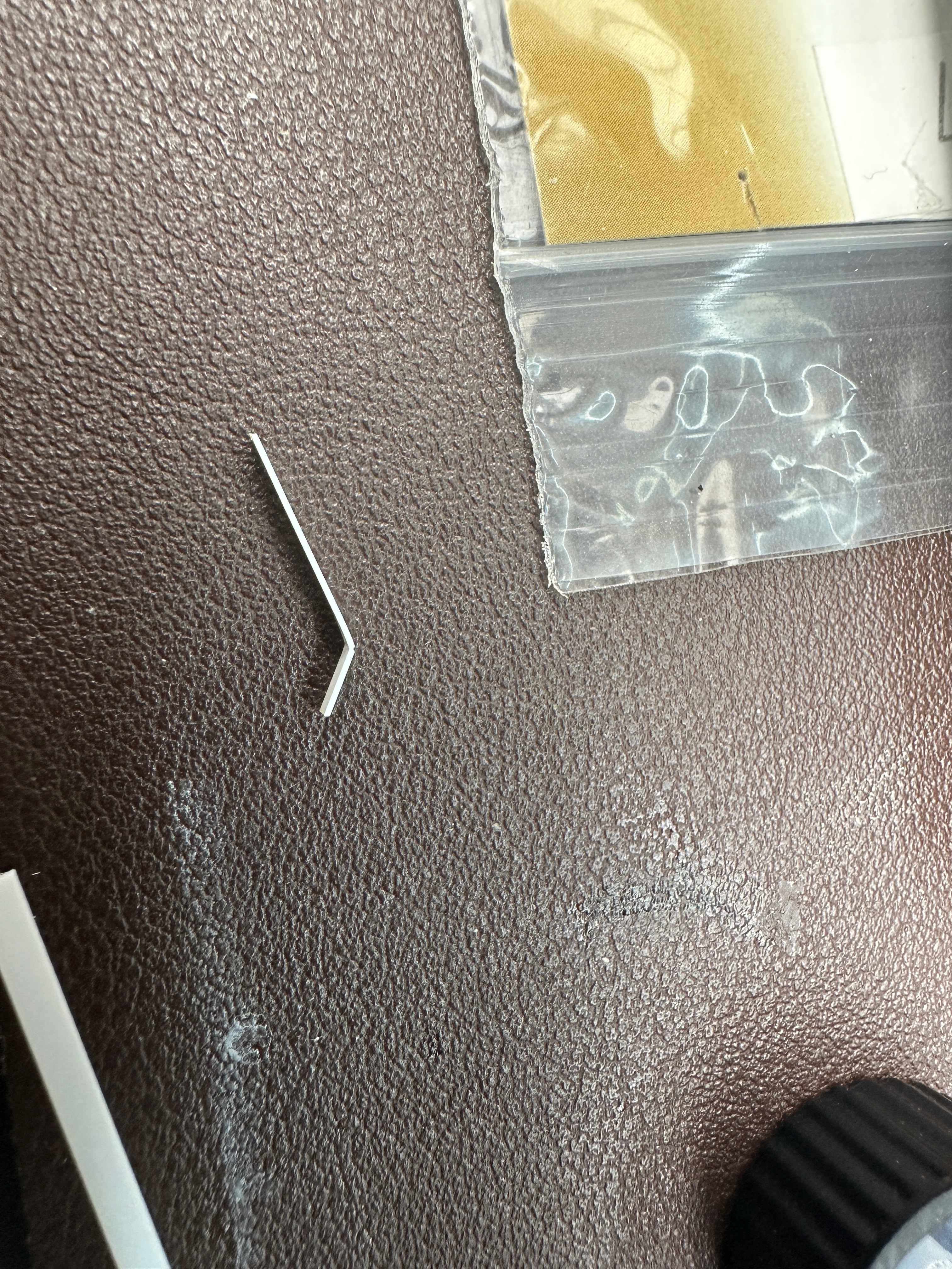
I also took the time to replace the oversized brake chains while I had everything apart. I covered one way that I've installed chains on the RS-2s here. In this case I used .006" wire and instead of a small hook, I used a long "U" and twisted it after attaching to the chain. Each one was slightly different.


On the last one I experimented with using some of the extra copper wire trimmed from the decoder. I removed the insulation, and used the wire to attach it to the model, and then soldered the wire closed. It worked well and I'm likely to continue to experiment with that approach in the future.

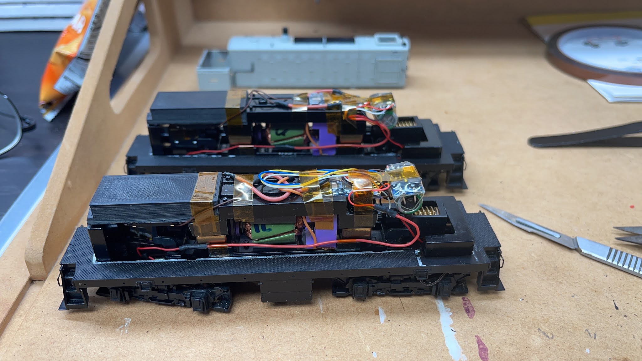
So here they are. Two naked Proto 2000 S-1s with sound (and tested). I try to be neat while installing decoders, but I'm not fanatical since I'm hoping I'll never see the inside of these again once they are finished.