
In my case, it's a relatively easy track to make. Since it's a stub-ended track dedicated to the scale, I'm assuming there's no gantlet track. I don't actually have any pictures of the scale track, but my research indicates that (in 1915 anyway) it was a 42-foot, 100-ton scale. I don't actually recall where I dug up that information, nor do I know if it was upgraded to a higher capacity.
We do have a picture of the scale track in Middletown, thanks to John Wallace. I don't know think he intended to get the scale track in the shot, but we've got it. This was (in 1915) a 34-foot 50-ton scale, and again I'm not sure it was ever upgraded. Nor am I aware if it was still in use in 1947. But it looks like it's in good shape in this 1947 photo, although the tracks beyond it don't look like they are well maintained.
If it was, I would guess it would have to have been upgraded above that capacity. We do have a track plan dated May 27, 1959 indicating the track is to be removed.
My guess is that the track scale here was used much like the one in New Britain. In New Britain, I'm convinced that the most use would come from shipments of trap rock from Lane's and Cook's Quarries. Perhaps there's some coke being shipped from New Britain Gas Light Co. In Middletown, there were brownstone quarries across the river in Portland, or just beyond. A 50-ton scale would be insufficient in 1947, and 100-ton barely so. I wouldn't be surprised if both had been upgraded by then.

In this case, you can see that it has a gantlet track, because it was built as a double-ended track, unlike the one in New Britain. Looking at the picture, the rails run along the top of the scale beams, and there are small metal rain shields that keep most of the rain out of the scale pit. between and outside the rails is wood decking that is at the same level that ties would be.
--
For a quick overview of track scales, they were situated at various yards on every railroad. Major yards would have one, and sometimes smaller yards, as is the case with New Britain and Middletown. L.C.L cars were not weighed, since the goods were weighed before loading. Regular loads from an industry, such as Stanley Works, were probably not weighed either. Instead, standard weights would be predetermined for their goods, such as a case of hammers. Bulk goods, on the other hand, such as coal, coke, or stone, would need to be weighed. Cars loaded at the bulk tracks would probably need to be weighed too. They would be weighed at the first scale en route to their destination.
The scale itself is housed in a concrete pit, with the rails (or one set of them if there's a gantlet track), running across the scale bridge itself. This is connected to a scale that is inside the scale house, and the operator uses weights and a slide, much like the old doctor scales, to determine the car's weight. They could do this very rapidly, even weighing cars in motion on some scales. Periodically, a scale test car with a known weight would be used to calibrate the scale.
The pit is covered by wood planking, and there are rain guards along the rail to prevent too much water from getting into the pit.
Railway Prototype Cyclopedia Vol. 12 has an excellent article about weighing freight cars and track scales.
Operationally, in my case YN-3 will drop of hoppers of stone to be weighed and then blocked for YN-1. For some sessions, the scale test car will be brought in and the scale calibrated.
--
I didn't want to just put wood planking on top of the ties on the track, it should be lower than that since there are no ties used. But how do I keep the track in gauge across that distance? Well, it's going to be similar to how I keep the track fixed and in gauge at the edge of the liftouts.
I started with cutting a 2" x about 6" piece of PC board. This is laminated with copper on only one side instead of both, but that's all I need. It's a very tough material to cut. The guy at the shop told me to just score and snap it, but that wasn't working for me, and I was afraid it would splinter. I took it to Chris to show him and get his opinion, and he just snapped it. I'm still having trouble snapping it, but I've found that if I score it on both sides and use pliers, I can get it to snap. I also found that after I get the score started (and all the way through the copper) with a utility knife, that a razor saw works better to get the cut deep enough.
The PC board is a sub-base that will have PC board ties soldered on top, and the rail will be soldered to those. For the lift out, these ties will replace the plastic ties. In this case, though, in addition to replacing the plastic ties, they will run parallel under the rail, instead of perpendicular as railroad ties. This is what will maintain the gauge through the scale track.
Note that on my layout, I have a thin layer of craft foam that covers the entire deck. When I first started laying track - in the helix no less - I used N-scale cork to reduce the noise in the helix. I continued that onto the main deck, since the roadbed in New Britain is pretty flat. As it turns out, I probably shouldn't have used roadbed at all. So I needed to fill the spaces around the track to bring the ground up, and started using the craft foam.
When building Whiting Street, instead of using cork at all, I decided to just use the foam for the entire deck. It works well, and I think will help reduce noise.
It's important in regards to this project, because it's the same thickness as the PC Board, and I'll cut out the foam where the scale track will go. As long as you're using roadbed for your track, this will work, although you might need an additional layer of material under the PC Board to bring it up to the correct height.

Here's the PC Board

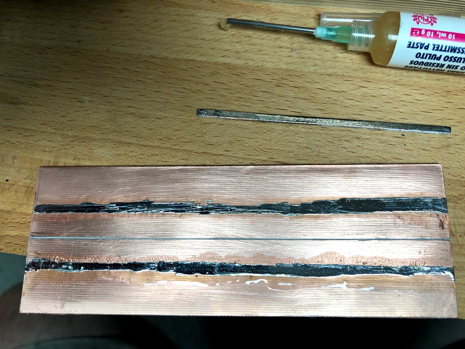
It's not pretty, but here are the two rail lines tinned. I'm using a no-clean flux, something I recommend every model railroader has because I'm finding that for some of my feeders the solder joint and plastic ties have been eaten away by flux that wasn't fully cleaned.


It's hard to solder and take pictures at the same time!
Tinning the ties is a challenge. I found I could put flux on the length of the tie, put a blob of solder at one end, and use a small file as a stop. I could hold the file in place, and smooth the solder down the length of the tie without burning my fingers. This approach of smoothing the solder also worked on the larger board.
I had some scraps of scribed wood, and used that as the deck. It needed two layers, and for now the top layer is wider and longer since it should be 2" x 6" decking, not 4" x "6". Most likely this will be cut back when I build the concrete edging that surrounds the pit.

You can also see a test piece of track with the ties removed. I found that the PC board ties are right along the inside edge of the rail base. It will work fine, but if I were to do it again I'd move the PC board ties in slightly to better center it beneath the rail.
Normally I'd probably try using the Proto:87 Stores etched tie plates. But since they would be hidden by the rain guards I don't need to worry about them here. I'll use a similar approach to build the engine servicing pits and will try them there.
Normally I'd probably try using the Proto:87 Stores etched tie plates. But since they would be hidden by the rain guards I don't need to worry about them here. I'll use a similar approach to build the engine servicing pits and will try them there.


After gluing the decking with the usual Aileen's Tacky Glue, I turned it upside down and weighted it with a power driver.
Really impressive final result in person - but now seeing the construction process, I'm even more impressed. And the tracks beyond the scale look about the same as all the other tracks in that yard, so I dunno that we should infer too much from their condition :^)
ReplyDelete