Friday, November 2, 2018

New Britain Gas Light Company

Yet another project!

I've been looking forward to building (at least one of) the gas holders for the New Britain Gas Light Company. Initially I was hoping to build the main one, which is about the size of a 5-gallon bucket if made to scale. I wasn't quite sure how I'd make the tank, but have some ideas.

But the Walthers model came up on sale, and I figured at the very least I could use it as a stand-in. There are a few things I don't like about the Walthers model:
  1. The walkway and ladder. The ones in New Britain don't appear to have a walkway, and stairs go to the top of the structure.
  2. The Walthers tank is one course too short, making the structure as a whole look too squat.
  3. The model as a whole looks short and squat. Dimensionally, it's about 1 1/2" too small for the diameter of the tank compared to the small tank that's in the location I'm modeling (the bigger tanks have been pushed off the layout).
  4. For some reason, the higher courses of the tank use smaller panels. That is, it appears it was constructed out of smaller sheets of steel for the higher courses. I don't have any pictures that are clear enough to see if this would be accurate or not, but I'm not sure why they would construct the tanks out of different size sheets of steel.
  5. To me, it looks like each course of the tank is stepped back too far. Again, I don't have good pictures or measurements, so this could just be me.
  6. There may not be enough supports around the tank. Like many of my issues, this might be an accurate representation of the tank they used as a prototype. If you look at pictures, there were lots of variations (especially in the framework) in the tanks that were built world-wide.
  7. The general detail (such as the bracing detail) is a bit lacking. I'm also trying to figure out how to better model the wheels that run along the tracks when the tank raises and lowers. The tank is right at the edge of the layout, and therefore very visible.
Here's the picture from the box of the Walthers kit:


And here's a picture of one of the holding tanks in New Britain:


Overall, my preference is for folks to see the structures and recognize them for what's being modeled, rather than seeing "the Walthers kit." Aside from the size itself, the major visual issue is the two courses of bracing versus four on the prototype.

As it turns out, the way the kit is designed, it's not all that difficult to address most of these issues, I'll probably tackle some of the detailing stuff later. Here's a look at how I address the major points:

The kit comes with two sets of main supports. One makes it look like the tank is nearly full, the other with the tank lower. Using the supports for the higher tank position, I cut off the very bottom, which is designed to fit into slots in the base.


I then cut off the bottom portion of the other main supports. I file both to fit together and extend the height of the main supports. I also cut off the top of the extra supports, to extend the top of the structures as well.


The lowest course as designed leaves enough of a gap between the tank and the support to squeeze in another course. This is the model half-built, and here it is with the tank completed, which required a second kit to get enough pieces for the extra tank course. I suppose I could have tried casting the part, but it seems like the time and money for the making the mold and casting the resin wasn't really going to save anything vs. getting the kit now while it was still on sale. In addition, I have other parts in case I need them.


For now I've tacked on a few of the Walthers supports with the center horizontal bracing removed. It doesn't look too bad. I think that the vertical supports may be a little too high, and I might lower it so the bracing reaches the ground, but on the Walthers' model and a lot of prototype photos I've seen, the lowest course doesn't have any bracing because it doesn't move. 


But overall, I like the changes. The proportions look better to my eye, and the number of courses of both the tanks and bracing match the prototype photos. I'm considering replacing the horizontal braces with channel as seen in the prototype photo, and I might scratchbuild the bracing altogether so it ends at the top of the first course. This would also allow me to end the bracing at the top of the first course, and will also make the individual sections of bracing proportioned more like the prototype. 

More to come!

Monday, October 29, 2018

Scale Track Part IV

So the building is pretty much done for the Middletown Scale House. I also needed to build the scale track itself. The process is the same basic idea as what I did in Part I and II for my scale track, except that it needed a second row of PC Board ties for the gantlet track.


A few things I decided to try a little differently. First, I noticed that the PC Board ties weren't centered under the rail on mine. So I first drew, then cut each line. I cut it all the way through the copper because it would also separate that strip from the rest of the copper, requiring less heat and more control when tinning.

One rail was placed with the PC Board tie at the edge of the line, and the opposite rail was just covering the line with the same edge to ensure they were better centered under the rails.


I then went through the process of adding the boards and weathering them. Note that there are a few small pieces at the end of the scale tracks to provide the 2' clearance at either end. All of the end pieces are overlapping so I could saw them even together.


The process of decorating was similar, but this time I applied the Pan Pastels while the stain (ink) was still wet. This worked better I think. I then sanded the whole thing to reduce the amount of color and brightned it with the neutral gray tint again.


When looking at the picture, it's clear that the scale house is white. I'm on the fence as to whether I think the framing is brown or green. Brown would have been the most common, but it really looks like a dark green to me, and NH Hunter Green seemed like a good choice. Chris liked it, so that's what matters. I haven't weathered the building at all yet (and still need to finish the roof).

So this part of the process was, overall, very similar. There is one thing that I thought of after the fact, which might have been more important than I would have thought. I could have tinned the tops of the PC Board ties before soldering them to the main base. It wasn't a big deal tinning them in place, but would have been easier if they were already done.


So the gantlet track itself is made from two Micro Engineering turnouts, with all of the ties (and frog) removed just past the jumper wire. Because the through track doesn't have storm guards, I used some etched tie plates I had on hand from Proto:87 Stores. These are actually turnout ones, and longer, but the longer part will be beneath the storm guard and not visible.
The flux was enough to keep them in place, and they can be soldered. I didn't tin them, just pressed the track down and soldered the track and tie plates to the PC Board tie at the same time.

I did the straight through rail first (based on the photo, the through rails were straight and the ones farther from the scale house), the one farthest from the scale house. I then did the scale rail on the same side of the center line.

I then used two track gauges to keep the rail in gauge while soldering each of the other two rails. The distance between the through track and the scale track is within the prototype range, and was largely dictated by the turnouts themselves. Because the points are so close to the scale track on the prototype, I cut all of the rails on the turnout to match the shortest rails so the track joint would be in the center of the scale, and I wouldn't have to use any extra pieces of rail. I didn't use rail joiners, I just aligned the rail while I soldered it. I also painted the track with my standard Rustoleum Camoflage (Brown) before installing it.


So the problem I have is that the PC Board itself has warped. The ends curve up. I don't know if it was the many applications of heat, or what, but it did. This is a single-sided board, so I don't know if one with copper on both sides would have been better. But I do think that had I tinned the PC Board ties first it might not have warped, or not as much. Chris and I have both decided it's workable, and once it's attached to surrounding trackwork it shouldn't be a problem. It's just a bit annoying that it did.

I'll be putting it all on a styrene base, finishing the concrete frame around the pit, and doing the roof and windows when those arrive. We'll be able to install it on Chris' layout soon!

Friday, October 26, 2018

Scale Track Part III

As I mentioned, Chris needs a scale track for his layout. While the Blair Line model I used is a nice kit, the main thing I didn't like is that the floor is a thick piece of wood that ends up flush with the sides. While you can (and I did) paint and weather it to look like a concrete slab, if it's a foundation it should be inset a little bit. In addition, based on measurements found online, I think that the board-and-batten siding uses oversized boards. Overall, I also prefer working with styrene than wood.

But really, I figured it's a simple little building to try my hand at scratchbuilding.

After going through the Railway Prototype Cyclopedia article, I realized I had missed that there is a 2-foot clearance around the scale itself, including the ends, within the scale pit. Which means there is at least 2-feet of wood boards between the end of the scale and the end of the scale pit. It also allowed me to ensure my measurement on all sides were within the standard.

So I started by taking rough measurements of the completed Scale House and cutting out the basic parts.


The basic parts and their scale dimensions.


Then I plotted out the windows and the door. Since the windows will have a frame, cutting out the side windows right to the corner won't be a problem. The same thing in cutting the front window from the top.


Board and batten siding can be made from a lot of different size lumber. But the dimensions I went with is essentially a 1" x 10" main board, with a 1" x 4" batten. The space between the battens works out to about 8" so I drew lines at 1' intervals.


I decided on the dimension in part because of what I thought looked good with the options I had on hand, and also what closely matched the dimensions noted on construction sites online.


So I marked the lines on all the parts, and started cutting out the windows and doors. I then completed the battens on a couple of pieces to see how I liked it.


You'll note that the side of the building has been redrawn with a new window location.


And the door has been moved to the back. Why? Because I wasn't really trying to recreate the Blair Line model. I want to make the structure that was there. Of course, we only have a (very) partial shot of the scale house in Middletown.  Here's John Wallace's photo again:


I've decided that since most scale houses had windows on both sides, and I think a door would be taller, that the frame on the side is a window. It's pretty much centered on the side, so I moved the windows on both sides. Which means the door needs to be moved to the back. So part of me says the door would be on the side, so you're never stepping out of the building into the way of a moving train. But the general need for the windows makes a door on the back logical.


The other New Haven scale house picture that I could quickly put my hands on is this one. I've seen others, and I can say every once is a little different. Some had the angled corners like the Walthers model, and others were this simple rectangular shack. Since this looks quite similar to the one in Middletown, I'm using it as a guide as well.

Of course, the other factor is that this one has horizontal side sheathing, and looking at the Middletown photo it looks like vertical boards but no battens. Since it's for Chris' layout, I figured I'd see what his preference is. Both of us agree that's what we think it looks like. So here are the pieces cut out of some scribed wood I had on hand.

Note that on the styrene version I decided to cut the large window opening lower, and the piece I cut out has been moved up to frame the top of the window.

The styrene parts make a nice template, and I may decide to complete that structure eventually. But for now I'm working on the wood one.

So it seems as good a place as any for a few comments on materials. I like the idea of using wood because you can stain it and sand it to weather it like I did on the deck of the first scale track. Stain doesn't penetrate styrene, and sanding styrene after you've painted and weathered it just exposes white styrene. So there are some interesting finishing and weathering approaches with wood that you can't do in styrene. In addition, cutting out windows in wood is much easier, as it's a softer material than styrene. However, wood has a grain that styrene lacks. Cutting across the grain is much different than cutting with it, and in most cases when cutting against it I found a razor saw a better tool when I could use it.

Styrene, on the other hand, is easy to cut with the score and snap method, but that can't be used for the first three sides of a window. I also find that when trying to cut all the way through styrene (instead of score and snap), even with multiple passes, the result is an edge that requires filing to finish because it's not perfectly straight. But the biggest benefits is that it doesn't warp like wood, especially thin wood. Paint and glues have more than enough moisture to make these significant issues. Thin styrene is stronger as well. Furthermore, gluing styrene is both simple and strong with styrene cement that "welds" the parts together. While the old adage is that when gluing two pieces of wood together, the joint is stronger than the wood is true. The problem is, the wood we typically use in modeling is very soft. So a layer of wood can easily slough off with the glue.


So you'll note that after painting with a craft acrylic, the wood has warped considerably. Especially the pieces with a window or door cut out. I knew this would happen (and that this wood was too think for structural integrity anyway), but I didn't want to strengthen it until after painting...


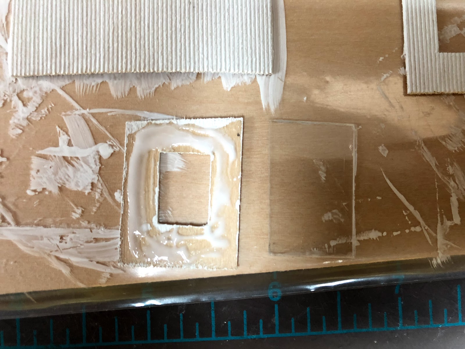
So I could use clear styrene for both structural strength and as window glazing.


Since I hadn't determined exactly how I was going to assemble the model, I cut the styrene so it was smaller on all 4 dimensions. This allowed more flexibility in assembly.


I used large 8' x 8' pieces to act as both a frame to assemble it, and the foundation of the building. 


Because the primary interior structure is the clear styrene, all of the window glazing is done. I chopped up some old Walthers windows (what I had on hand), but decided they were too coarse for the model. So I have several other options on order and I'll decide which I like best. I'll be able to paint them before installation so I don't have to worry about harming the glazing.


I haven't finished the roof, obviously. The door is scratchbuilt. The interior on the back is regular white styrene since there's no window. I first drew the pattern on the door and started by installing the first horizontal piece at the top of the door, then using a full piece of strip styrene one of the vertical pieces (the long "handle" makes it easy). Once the glue had done it's job, I cut it to length (to where the next horizontal piece is), and did the same for the other two verticals. Then I added the horizontal piece, and used the same approach for the bottom half of the door. I drilled a small hole and used a piece of wire for the door knob.

I also used strip styrene to finish the corners and fascia and the frame around the door. I will do the same around the windows once I've installed mullions.

Next: The next major piece was the scale track itself. Unlike New Britain, it's a gantlet track in Middletown. Something I had wanted to try.

Monday, October 22, 2018

Weathered Steel

Well, I thought I was done...

Chris needs a scale track too, and there were a few things I thought I'd do differently after I finished the first one. So there is more to come.

I did start the storm guards for mine, and I'm really happy with the finish I came up with. I started by painting it with a Rail Tie Brown paint marker. This is Floquil, which isn't readily available anymore, but Woodland Scenics makes them. At some point I plan on comparing colors to the much larger selection available at art stores too. In this case, the exact color doesn't really matter, I'd just suggest starting with brown.

Since styrene is pretty smooth, trying to brush (or in this case, draw) it on tends to streak a lot. Since the tip on this one was well mashed anyway, I just smushed it straight down like I was stippling. I then immediately started using Pan Pastels in the same manner, with neutral gray shade, and a couple of browns to get a random slightly rusty look, then brightened it with the neutral gray tint. I also did some on a larger sheet of styrene to see how it would work over larger areas, and to make it easier to see.


Here are some in progress photos:


These are all completed, but at slightly different angles. The lighting makes a big difference as you can see. The wood skewer in the last photo is there just to give the camera something to focus on.


I'm really happy with the results, and it looks even more amazing in person specifically because the angle and lighting really highlight the variations well. I'm going to play around with the technique for the interior or gondolas and hoppers, and I'm also experimenting with different color applications for concrete and asphalt.

Friday, October 19, 2018

Getting Ready for More (or Less) Operations

In past operating sessions, the layout has operated well. It's more than exceeding expectations in regards to creating a prototypical operation, complete with a freight agent/yard master. But the reality is, while I know exactly what I want in terms of paperwork, waybills and such, I'm not there yet. In addition, it was also clear that the amount of work can be overwhelming for folks not used to as much switching work. Combine that with the fact that there will soon be a new section of the layout to start testing and working into the ops sessions, it's a good time to create a scaled-back operating session.

So that means reducing the number of trains, and the number of cars to work. While we could just choose some, why not model the traffic in a different year?

In the busiest years, such as early 1947, the amount of work is substantial:

  • OA-4, OA-6, NY-2, and EA-2 leave cuts of cars overnight.
  • NY-4 and HDX-5 bring additional cars in the first two hours (30 minutes on the fast clock).
  • Outbound cars have to be blocked for 6 trains: YN-3, HDX-5, ANE-1, AO-5, OA-4 and YN-1. 

Along with the freights, there are 8 passenger trains through the day.

It still boggles my mind that there was this much traffic through the region. But it is a lot of work to manage. In addition, right now we need to be testing the mechanical aspects of the equipment and layout so I can keep moving with the scenery base. It's also been a while since we've had extensive testing of the layout. A couple of years ago, it was getting regular use, either with ops sessions, or testing and preparation. That hasn't happened in a while.

Tangent: Modeling Multiple Years

To me, I'm not just modeling the prototype equipment, track arrangement, structures, and so on. It's been said, "if you're modeling the 1950s, you're modeling 1959 poorly." I understand the sentiment, because if you choose to run equipment that left the roster in 1950 with equipment that didn't exist until 1957, then you aren't modeling 1950 , 1959 or any year in between accurately. And I agree with that assessment.

But it's also quite possible to model the history of the railroad. The infrastructure in New Britain, that is the trackwork, didn't change (much) between 1946 and 1954 when the mainline was single-tracked:
  • At some point in that period, Farm Yard, a small yard across Myrtle Street was reduced in size, but I didn't have the space to model the yard as it was before that time.
  • Yard tracks #15 and #17 were removed c1953 and turned into a parking lot, although I don't have an exact date as yet.
  • Lockshop pond was also filled and turned into a parking lot. 
  • Several shops and industries changed, particularly in the Railroad Arcade.
  • City Coal and Wood was torn down, possibly between 1953 and 1954, it was definitely there in 1951.

I'm planning on seeing if I can build an insert to cover Lockshop pond. If it works, I'll probably build two - one when the parking lot was being built, and one as a parking lot. It might be a bit more difficult to do the same for the two tracks that became a parking lot in the yard, although the leads remained east of Elm St.

Since the Railroad Arcade will be a facade to be connected to the layout for the purposes of photos, it's easy enough to construct it as modules so I can add the correct storefronts for a given year.


City Coal & Wood behind L-1 #3229 c1946 from a Paul Wales video. 

City Coal and Wood will be made removable for the same reason, because it will be very noticeable when it's gone.

Cars and billboards can be switched, and the roster of locomotives and freight cars can be adjusted for the year. The variety of locomotives is one of the particularly interesting thing about the range of years I've selected. The only equipment-related issue that's not easily addressed are the reweigh dates on freight cars. These aren't typically something easily noticed while operating, but I can be selective when taking photos. Although you only see one side of the car during an ops session, so I could put a different reweigh date on each side.

Anyway, the point is, by modeling multiple years, and paying attention to the details that changed in that period, you have the opportunity to model the history of the railroad over that period. That also includes modeling the history of operations over that period too, and in New Britain that changed quite a bit.

For example, instead of modeling late summer/early fall of 1947, we can jump to late summer/early fall 1949. What impact does that have on operations?
  • OA-6 and NY-2 leave cuts of cars overnight.
  • NY-4 drops off a second cut of cars at Whiting Street Yard at the start of the session.
  • There is no local freight (HDX-5)
  • Crews need to block cuts for 3 outbound trains (YN-3, AO-5, and YN-1)
  • There's the same 8 passenger trains.
It's also much easier to model in terms of motive power.

1947 Motive Power
Two 44-tonners + Stanley switcher (3)
Two FA-1 A/B/A sets (6)
Two S-2s (2)
K-1-d
R-1-b
I-2s and DL-109 or I-4 for passenger trains (3)
That's a total of 16 locomotives, with at least 3 steam (not including the Stanley switcher)

1949 Motive Power
2 44-tonners + Stanley switcher (3)
FA-1 A/B/A set (3)
2 RS-2s (2)
2 RS-1s and a DL-109 for passenger trains (3)
That requires only 11 locomotives, and all diesel.

Of course, I love the mix of the '47 session, with big and small steam, along with road and yard diesels in a variety of paint schemes.

If the session ends at 7:00 pm, we could eliminate an A/B/A set and the R-1-b, bringing the total to 11. But in the 1949 session it eliminates the FAs altogether, leaving a total of 8 locomotives.

1949 Schedule (for shakedown sessions and open houses)

7:00 am to 7:00 pm
Even-numbered trains are eastbound, odd-numbered trains are westbound.
  • 7.00 am: 12-15 cars on Track #5 at N.B. Yard, and 12-15 cars on Track #6 at Whiting St. Yard. 
  • 7.05: NY-4 drops 5-6 cars at Whiting St. Yard.
  • 7.32: 444
  • 8.35: 446
  • 12.43 pm: 131
  • 2.00: YN-3 drops off cars to be weighed and cars for OA-6; picks up cars blocked for Berlin, Cremo Brewery, North Haven, Cedar Hill, New London (CV) and Worcester.
  • 4.05: 157
  • 4.41: 463
  • 4.45: Freight house closes, cars can be pulled at 5.00 pm.
  • 5.43: 136
  • 7.00: Session over, cut on Track #5 at N.B. Yard blocked for Waterbury, Maybrook loads, Maybrook empties. Cut on Track #6 at Whiting St. Yard blocked for Speed Witch, Philadelphia Transfer, Enola, New London (CV), and Cedar Hill.
If we want to, we can run AO-5 at 7.25 pm and YN-1 at 7.30 pm. They pick up the cuts of cars on Track #5 and #6 respectively, and what will make that interesting is working the individual blocks into the existing train.

One final train, passenger #472, is schedules for 9.20 pm, and that one is unique in that it picks up a baggage car that has been sitting in front of New Britain station all day and is full of storage mail.

Overall it's a very easy session to be prepared for in terms of equipment. But even better, it will allow us to focus on testing the switching jobs, which is the primary work on the layout. We've made changes to Stanley Works (more track, and we think we have a better idea of how they operated and interchanged with the New Haven), and Whiting Street makes a big difference in terms of work for the two New Haven switchers.

All of this hides the fact that there's a lot of work during the session, switching out 50-60 cars. The switch crews are classifying, setting out, picking up, weighing some cars, and blocking the outbound trains.

Crew

I've been considering splitting the Agent's job into an Agent and Yardmaster job. The Agent would continue to handle the waybills and write out the list of cars and destinations, along with the list of cars to pick up. The Yardmaster would organize that work into switch lists for both NH switching crews. I think that it's more prototypical and will help take some pressure off of the Agent and the switching crews. In other words, in terms of understanding the layout and how to operate it will really require one fully-qualified yardmaster.

  • Freight/Station Agent
  • Yardmaster
  • Engineer and Brakeman for each switching crew (Two NH and Stanley Works)
  • Through train Engineer/Conductor.

The through trains probably don't need two crew members most of the time, but if there is somebody free a brakeman would help when they are dropping off and/or picking up cars. The layout could be operated with as few as 5, and as many as 9.

So that's the current plan. A reduced operating session, probably with simplified paperwork, to get things going sooner rather than later, and hopefully frequently too, for testing purposes. Because once Whiting Street is in, I want to be working on all of the ground cover, ballast, roads and vegetation as soon as possible.