Wednesday, May 19, 2021

Modifying the Tichy Flat Car Part VII

In the first post I showed how I modified the deck and assembled the basic kit.

The second post covered scratchbuilding side sills and measuring and installing stake pockets. The third post covered how I was handling the rivets with an addendum from my buddy Bill Gill here. The fourth covered some additional prototypes. Fifth was the underframe on the NH car. Sixth was the end sill and deck of the NH car.

The impetus for this particular project was a photo of a T&P flat car which also includes prototype information for that and similar cars.

Since I had the CofG kit, I decided I might as well finish that one too. The set of decals comes with a diagram for the car, and it's about a foot longer than the Tichy model. Should I bother?

Sure, why not? In this case it's just adding a single board to the length. As I was reassembling the deck, it occurred to me that instead of just cutting it in the middle and then cutting a single board from a spare deck, it would have been easier to cut out a chunk of, say, four or six boards and replace it with a piece of five or seven boards. That would have been much less fiddly than trying to square and insert a single board.

They have some photos online of when they moved the car and a work session. It is noticeable that the fishbelly center sill wasn't as deep as the Tichy model, much like the NH car. I thought that the center sill from a Branchline (now Atlas) ACF/URTX reefer would do the trick. It's about the correct length after I added the extra board to the middle:

This is too deep, here it is compared to a spare bolster:

It looked like I could cut along the rivet batten at the bottom and it would be just right.


Then it was a matter of filing the slots for the bolsters deeper to accommodate the change. I also trimmed the tab off of the bottom of the crossbearers (that fit into a slot in the Branchline underframe):


Then I remembered that the center sill sits below the level of the crossbearers which sit on top of the stringers (when assembling the model). So those tabs probably could have stayed.


I used some strip styrene as a spacer while assembling it. When looking at the photos of the work session, it's apparent that there are two stringers between the crossbearers, so I filed slots to allow that placement:


The crossbearers and stringers are a little short, but not visible when the car is on the track, so I decided not to worry about it. For the other stringers, I just used scale 4"x4" instead of building channels:


The end sill is a channel facing outwards, but deeper than the one on the Tichy model. So I fabricated a new one from styrene:


After applying that, I cut out the coupler pocket:


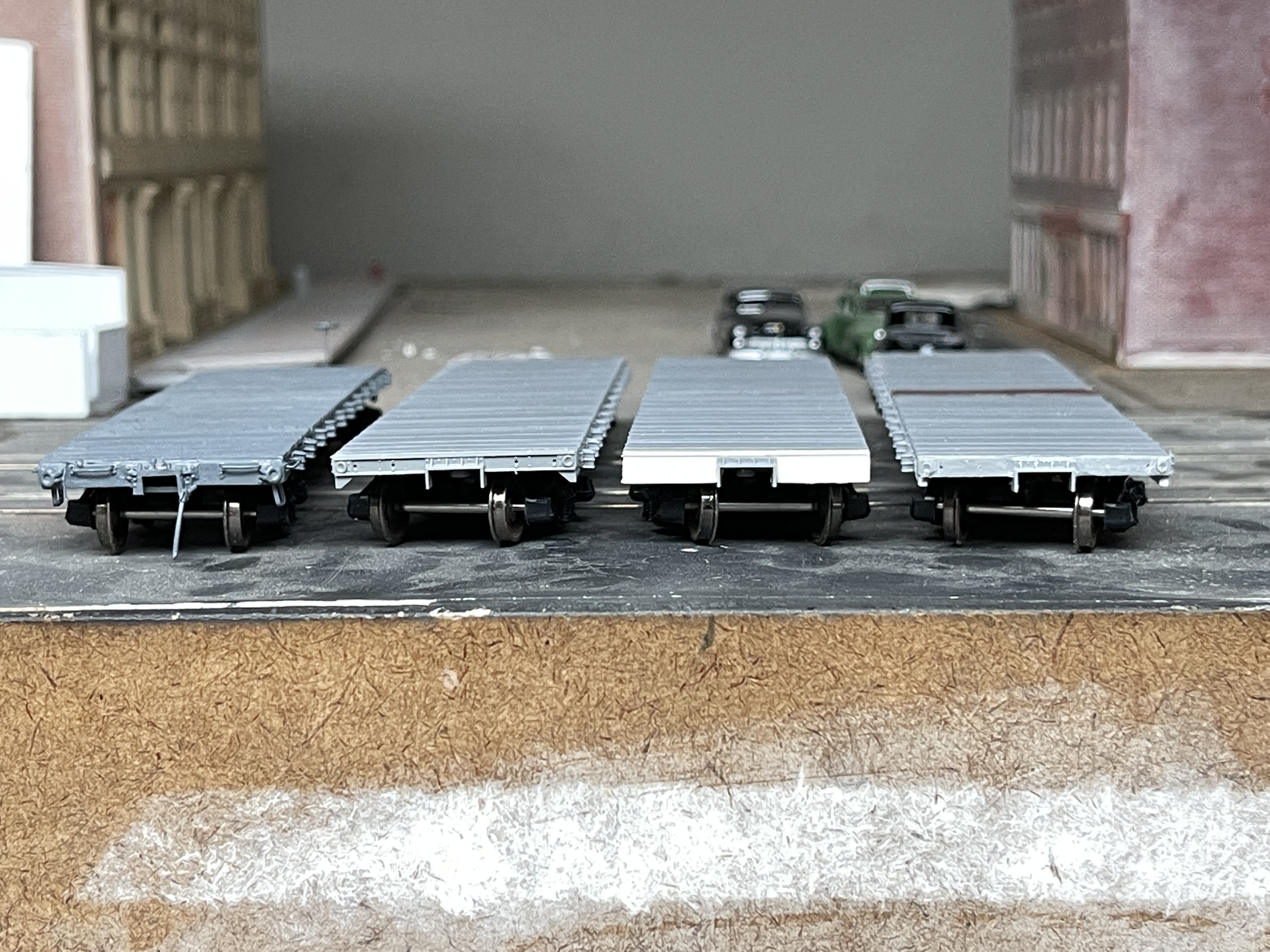
The shallower center sill is quite evident next to the unmodified Tichy kit:


Four different ends. The NH on the left, the NC&StL (unmodified Tichy) next, the CofG one (with details to be added), and then the T&P one which is the Tichy end but with the channel flanges removed.

Note that I used the Tichy striker casting for the CofG end. It's not a perfect match to the prototype, but was a simpler solution than scratch building it.


I didn't have a good shot of the side to figure out the stake pocket spacing. But I also don't see many extra rivets in the photos. It occurred to me as I was experimenting with spacing that if one side of the stake pocket lines up with the crossbearer or stringer, then the rivets for the underframe components may have also been used to attach the stake pockets. So I used the underframe as a guide for the spacing. Since it seemed like all of them had similar spacing for the first two stake pockets from either end, I retained that spacing, then spaced the rest according to the underframe.


I still have rivets, grab irons, and other details to add, and I'll be doing the rest of those features on the other flats too. I really like the way this one is coming out. More to come.


Monday, May 17, 2021

Design - Greg's Layout

Dick and to a lesser degree I, among others, have been helping Greg design and build his layout. The space is relatively small, and complicated by the location of the mechanicals in the room.

Greg has built the Milwaukee Everett St. Station and train sheds (they look awesome) and owns four different versions of the Hiawatha, so that is a big part of the layout, but also wants to include New Lisbon, WI, which is somewhere between 150 and 200 miles away. He'd also like to be able to have some sort of operations so he can have folks over to run it.

It sounds like a very interesting concept for a layout.

He has a roughly 22' by 14' room to work with. However, the mechanicals are located in a position that means the main portion of the layout really has 11' by 14' to work with. While we can fit some things around the mechanicals, it greatly limits options. Oh, and it has to be single level with continuous running.

For a prototype-focused modeler like me, this is a challenge to wrap my head around, and from a layout design perspective a seemingly impossible task in the space and restrictions given.

Layout Design

When starting from scratch, my approach is usually to sketch out how to maximize the benchwork in the room. I start with a minimum 30" aisles, and assume up to 30" deep benchwork and start from there. It just helps me visualize where we can actually put track.

I did some early sketches to see what we could do with a helix. Although I'd prefer to see the trains as much as possible, I am a fan of a using helix to create distance between scenes where it makes sense, and it certainly would make sense here. Dick even drew one up with a helix around the mechanicals. But Greg wants to keep it to a single level, so those are out.

In this case, there isn't enough room for a peninsula with a loop, so it's pretty much a rectangle around the main part of the room. 

The next thing to consider is where the desired key scenes will fit on that benchwork. Greg had already worked out a concept with the Everett St. Station against the 14' foot back (south) wall, which is logical. He hopes to have some industry to operate, and then back across the room with something representing New Lisbon.
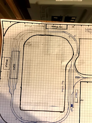
Although not the best picture of it, this is one of Greg's sketches. The rectangle at the top is the electrical box. Dick designed a swing out here to allow access, and benchwork has been built along the three walls so far. The rectangle in the lower right corner is where the mechanicals are located. 

The S-curve between the electrical box and New Lisbon also happens to be where a lift-up/out or some other approach to provide access is needed. This doesn't show any sort of staging at this point, although there is room along both sides of the room off to the right. 

The wye is going to be the biggest challenge, and I don't trust my drawing/math to know that I can get it right on paper. So we mocked up the wye with the Peco turnouts he's using, and 24" radius for the legs since we can't reasonably go any tighter than that. The goal would be greater. I have a few pieces of 24" sectional track that I use for mockups like this so I know that we are working with a true radius rather than an unintentionally optimistic one that I bend from flex track.

With our measurements, we determined that there are only three places it would fit. Right where it is, moved to the lower right corner of that section of the room so the stem of the wye goes down the other side of the mechanicals, or by moving New Lisbon to the other (right) side of the mechanicals altogether and turning it so the leg of the wye is in the same location, but facing the other direction.

Operations

But the other thing that I'm always mulling over is how the layout will be operated. This is partially a question of the movement of trains, but also where the operators will be, how they'll move through the space, and how best to maintain the illusion of a real railroad, rather than one just built in your basement.

There is an important question that I find is often forgotten as we design a layout:

What will the operators do while operating?

We often focus on the track arrangement, and maybe the specific trains, and even ensuring you have space (wide enough aisles) for people, but we often don't think about what those people will be doing for 3-4 hours or more. 

I think most of us are used to the approach of following the train for ops sessions nowadays. Each operator/crew is assigned a train, runs it through its job, and then takes another train out if there's time. Chris' Valley and Air Line locals are great examples of this.

My layout, on the other hand, is more of a switching layout. Yes, there are through trains, but they are on the layout for only a few minutes as they come up from staging, stop at the station (or drop off/pick up a cut of cars), and then go right back to staging.

Chris had to contend with that very question after the fact, like so many of us do.

Both Valley and the Air Line locals both occupy a crew for a full session. But there's another local that serves two industries in Saybrook, plus interchanges cars with the south end Valley Local. That only occupies a crew for an hour at most. What would that crew do for the rest of the time?

But by adding in the heavy passenger and through freight traffic, another crew (split between the two staging yards) are also busy for an entire session and can handle that short switching job.

For Greg's layout, the answer for me was a 1941 Trains article on the amount of activity in New Lisbon that Greg had. It covers less than two hours of (very) busy activity, but I later found some timetables to verify that there would be a good amount of activity during the entire session.

The article about New Lisbon details how two through freights both stop in town, uncouple from their cut of cars to get coal and water, and then move their cuts into a siding to wait.

In addition, two passenger trains also come into town, get coal and water, and then back into two stub sidings and wait.

Two Hiawatha trains (100 and 101) then come into town, make their station stop, get coal and water, and then continue. The other four waiting trains then start to go on their way. 

In other words, it's a perfect arrangement for a railfan style layout similar to Chris' Saybrook scene where the trains enter from and exit to staging, and the operators are in a single location handling the movements of all of the trains. The Everett St Station scene also lends itself to this sort of operations, with lots of passenger (and freight) passing through, and a little passenger switching.

The connecting track between the two, when scenicked, can act as hidden staging to supplement additional staging. A train leaving New Lisbon can pull out of the scene and stop, and at some later point the Milwaukee crew acquires it and pulls it into the station.

By moving New Lisbon to the other side of the mechanicals, it also gives us room to build an industrial area on the west end of Milwaukee.

This all goes back to answer the question too - what will the operators do?

  • Crew #1 operates Everett St. Station and all trains, including passenger switching.
  • Crew #2 operates New Lisbon and all trains, including getting coal and water.

Both of these jobs are full session jobs.

  • We can also add Crew #3 that runs a switcher handling industries in Milwaukee.

Now we've got something to work with. Six crew members, all working in their own independent physical spaces, all with full session jobs. The distance between New Lisbon and Milwaukee feels prototypical, since you don't follow a train from one to another. In fact, the New Lisbon crew won't have any direct observation of what's going on in Milwaukee or vise versa. Other than keeping train lengths down, the scenes can be built and operated fairly prototypically and should be recognizable to anybody that knows the locations.

So I sketched up New Lisbon and while it will be tight with a few compromises, it will fit. The turnouts/crossovers may not be in those exact locations, but I tried to keep all of the important tracks for operational purposes.

Note that this is rotated 90 degrees to the right from the prior photo. The lift up/out will be a simple rectangular piece. Additional staging can be built to be semi-hidden on the left side of the Milwaukee and New Lisbon scenes, and also on the right hand side if needed. There will be a slight grade down to New Lisbon, and a grade up to the industrial area to allow the staging on the north end of the wye to go under that section to be hidden.

This uses 26" and 28" radii for the main tracks, and although they won't be exactly parallel, also for the station stub tracks where they will need to curve. In addition, the legs of the wye are 26" radius.

As you can see, the wye ends up about 30" away from the mechanicals, but anything else eliminates any possibility of modeling the station area itself, and to maintain the radii prevents it from moving any further to the right. All sidings, stub tracks, and staging tracks are at least 3 feet (one piece of flex track) long. That's quite short for passenger trains, but it's about the best we can do here. The only thing that's really missing is the dead straight trackage through town, and that's just unavoidable in this space.

The New Lisbon scene is a good example of how the track layout is crucial if you want to replicate the prototypical operations. With six trains meeting at the same location, and all getting coal and water while making their stops, you have to have at least four tracks long enough to move trains off of the main. Fortunately, two of them were stub tracks, which adds interest since you need to back passenger trains into both of them. There is a coaling tower at each end of town, one of which was built specifically for the westbound Hiawatha.

The Everett St. scene is at the top of the page (not drawn, obviously), and the peninsula in the middle will be an industrial location with lots of work.

This is just a sketch and recommendation, and as it's Greg's layout things may very well change as we help build it. But I'm pretty confident that this is the best (only?) way to fit New Lisbon into this space and we can ensure that he's able to model both of the key scenes that he'd like plus meet his goal of being able to have folks over to operate too.

Friday, May 14, 2021

Passenger Operations

I was recently going through a number of documents that I have regarding passenger operations. It's not something I have dug into a lot, simply because on my layout it's just a station stop for every train that comes through. But when researching what I had on the Conductors' Reports for the freight operations, I found that I had the information regarding Forms 1591-1595 for the Conductors' Passenger Train Reports.

I have three different copies of General Manual of Instructions for Conductors and Ticket Collectors.


This one dated February 1, 1937 is incomplete and only contains pages 25-34, 69-72, 111-121-A plus an appendix with a map. It also has a second, slightly different, set of 113-121 and the map which is evident because of slight formatting differences.


I recently acquired one of these other two. They are undated and, I thought, identical. It turns out they weren't. The Traffic Manager and Auditor are different at the bottom of the cover. 

At the bottom of most pages are notations indicating when that page was published. For example:

3rd revised page 71 - Eff. 1-1-44

Correction No. 137

Not all of them have this notation, and some that have a revision notation don't have the correction notation. But after looking through it, it seemed clear that the Correction No. was sequential and indicated the number of changes that had been made in the booklet as a whole over time. I was unclear whether the Revision No. indicated is was the 3rd Revised page in that issue of the booklet, or the 3rd Revision of that specific page. While pondering this, I noticed that the two later books weren't identical, and had a number of different pages that are easy to identify because of this notation. Curious, I made a spreadsheet to identify the differences.

It became clear that the Revision number was probably referring to that specific page. The book confirmed this and also another practice that I had identified in numbering the forms, but had never seen in writing.

INTRODUCTORY

(c) This Manual supersedes all previous Passenger Traffic Department and Accounting Department circulars. The instructions are issued in loose leaf form and all additions, cancellations and amendments will be published in loose leaf revised pages with effective date shown thereon. When page is reprinted the first time, it will be designed "1st revised page." Each subsequent reprint of such a page will be numbered consecutively, i/e/ "2nd revised page," "3rd revised page," etc. When there is not enough space on a single page for additions, changes, etc. additional pages will be added as may be necessary, and to which the same page number will be given, but in addition thereto, a letter in alphabetical sequence will be shown as "page 10-A", etc. On revised pages the symbol "*" will be shown against items which have been added or amended, but not against items brought forward to revised pages without change.

This entry confirmed the way the railroad identifies revisions of a form:

(g) Suffix number shown on forms after regular form number refer merely to the number of times that form as been revised; for instances, form 346-13 is the thirteenth revision of form 346. For this reason form suffix numbers are not shown in these instructions.

The section I referred to before, regarding the Conductors' Reports, is inserted in the books prior to the Index, and numbered from page 1 to 5. The Index uses Roman numerals for the page numbers (I-VI), and then the book starts at page 1 again. I find it interesting that it is inserted in two different books since it's not contained within the Index. It's the same format (size and number of holes punched) so it appears it was designed to be added to it, but for whatever reason was not incorporated into it.

Oddly, page V of the Index has the same revision and correction number in both copies, but differ significantly in their content. It is primarily a list of corrections, in one book from Correction No. 277 to 476 and in the other book from 400 to 583. Both are 1st revisions, Correction No. 276 and dated 7-1-55.

I didn't notice such an error elsewhere, but it seems like this is a rather important page to get correct...

The book is primarily concerned with the processes of collecting tickets, payment, and verifying that every passenger has paid (including checking the saloons). For example, I didn't realize there was a $0.90 surcharge for the Hell Gate Bridge that had to be collected if the ticket didn't already include it. The map I mentioned shows various non-New Haven routes for which passage over Hell Gate Bridge is free. The second (almost identical) version of the map doesn't reference the Bridge Arbitary at all, and instead is referencing free transfer privileges in New York and Grand Central Station.

Once I started digging, I decided it would be easier to make a spreadsheet and found that only about a third of the pages are the same across all three books. Another third is the same in at least two of them, and the final third is different in all three. I even started compiling a comparison of all of the differences but, while interesting, I decided it was an exercise better left for later (or someone else) since the minutia of changes in collecting tickets on the NH wasn't very relevant for what I'm doing.

Model Operations

Something that is often forgotten when operating passenger trains on a model railroad is that the time listed in the time table is the departure of the train, not arrival. Sometimes it will list both the arrival and departure. So to run on schedule it's important to arrive several minutes early, but not leave the station until the time noted on the Time Table.

From a modeling standpoint, there is little here that is likely to be used, but there are options. At RPI we experimented with some simple paperwork to simulate the basic job, and make station stops a bit more interesting (and probably last a little longer. 

In the bill box there were "waybills" for people and baggage. Each one had a train number, and either the number of people or pieces of baggage that got on or off. A simple table was used to track the number on the run and, if I recall, we experimented with either picking up or leaving the cards there for the next session. 

It would be easy to go a step further if one was more interested in passenger operations by using the actual Conductors' Reports, and replicas of the tickets and baggage check tags instead.

Model passenger trains are often run with just an engineer, even when the layout has two-person crews for freights. But with a passenger conductor, they could handle the tickets and complete the conductor's report. 

It would be educational, and interesting to me anyway, for a layout with long passenger runs. Particularly on our shorter-than-prototype runs, and makes the process more than just run-stop-wait and repeat.

At RPI, one of the few layouts I've run with very long (and frequent) passenger runs, there were often long waits after arriving at the station since the short runs (even with a fast clock) made it difficult to replicate travel time between stations. The paperwork helped fill these longer waits, and also drew attention away from them.

Completing such paperwork certainly won't be for everybody. But if your layout is particularly focused on passenger operations it seems like it could be an interesting addition.

Here's a variety of tickets, each of which is mentioned in the manual and serve different purposes. There are many others that I don't have copies of yet.


Exch 23
A ticket for cash fares beyond conductor's run to stations on:
B&A, B&M, and PRR. Also used for stop-over.


CFEX
To New York and return.
This is noted as a change effective 7-1-55. It isn't present in the 7-1-61 update.


OW3
A one-way ticket for all stations except Cape Cod Points.
Since there is text on the back of this one, here it is:


RT-3
A round-trip ticket for all stations except Cape Cod points.


Fu 2-X and LB-PSX
Neither of these are listed in any of the three books.
The first form looks like it is for furloughed military personnel. It's not dated, perhaps during WWII?
The second is for Pullman travel, which I think was needed in addition to regular ticket.


PA-861-2, -3, -9, and -10.

While the number after the dash is usually a revision, these all have different info on the front. They aren't listed in the books, at least under the forms, but the instructions indicate they are to be used to account for tickets that are not lifted (taken from the passenger). A physical ticket or form appears to be required to correspond with the report submitted by the conductor at the end of the run.

They had specific envelopes to return the reports/completed forms. Sleeping cars and club cars had separate envelopes from the tickets. I don't have any of these specific envelopes listed, but they can be recognized because they also have form numbers. This one is listed in the book as a plain envelope, small.


Wednesday, May 12, 2021

New Haven Videos

In a recent discussion on the NHRHTA Forum, I remembered a video I had seen a while ago that was relevant to the discussion. Of course, I couldn't remember the name of the video. I realized I hadn't collected those links here, which would have made it easier to find...

So here's some fun things to watch.


Capture of a video by Paul Wales, since released by A&R Productions
(Preview linked below)

Others (including better quality versions of a couple of these) are available from NHRHTA here.

New Haven Railroad: A Great Railroad at Work - A classic and comprehensive promotional film made in the early '40s about the railroad.

Southern New England - a fantastic promotional film focused on the new Alco FA-1/FB-1 locomotives. In color. Available in better quality from NHRHTA as Riding the Maybrook Line.

Memories of Steam in New England - as you might expect, it covers other New England roads as well.

New Haven 1950s Preview - Greg Scholl video, including scenes on the Highland Line.

New Haven Mainlines Preview - Greg Scholl video.

NH1 Clip - Preview of A&R Productions video New Haven Railroad Volume 1.

NH2 Clip - Preview of A&R Productions New Haven Railroad Volume 2 video featuring color films taken by Paul Wales, including some taken in New Britain in the 1940s and '50s. We had a preview of these films at my house before A&R received them to produce their DVD.

8mm Silent Films of Noel Weaver, Jr. An ex-NH railroader who always had interesting info.

16mm Silent Films - Later than my era for the most part, but still interesting.

NHRR and LIRR - Also later than my era.

NHRR Around Providence and Boston - also McGinnis era and later.

The Railroad in Franklin, MA - Joe Landry presentation with excellent footage.

1950s New Haven Action - more color films, these from William Sternitzke's collection.

1950s New Haven 8mm - Films by Alan Thomas, also from William's collection.

When Steam was King - Another color film, only the first train is New Haven. It's a baggage/mail train, and was relevant to the discussion. But since it was also the only New Haven train in the film, I hadn't remembered what it was called.

I'm sure there are some I missed, and there might be a duplicate or two in the list above. A Great Railroad at Work shows up frequently on YouTube under different titles.

The Greg Scholl and A&R Productions videos are available from many online (and train show) resources, so I didn't link any specific ones. I highly recommend New Haven Railroad Volume 2 by A&R of course, since it has a whole bunch of Highland/New Britain shots.

NHRHTA used to have a video containing Kent Cochrane videos. I have an extended cut of that, and hopefully NHRHTA will be releasing that in the future since it also features the Highland line and a little of New Britain.


Monday, May 10, 2021

RI Flat Car with Lumber Load


This is an undated photo, in an unknown location on the New Haven. In addition to the good view of the lumber load, there are a lot of chalk marks. With a reweigh date of 11-42, it places it in late '42 or sometime in '43, perhaps early '44. Looking very closely at the photo, I can see that the car was built in 4-30.

Researching the Car

Unfortunately, only the last two digits of the road number are visible. I don't have any Rock Island specific data or books, so how do I figure out what series of cars this is, and whether there are any appropriate models?

Checking the 1943 ORER, what options are there for an RI flat car with a 100,000 capacity?

  • 90000-90199 (53' 6")
  • 90200-91099 (new in this edition, page dated Jan 1943)(53' 6")
  • 92050-92999 (43')
  • 93250-93499 (46')
  • 93500-93749 (46')
  • 94000-94199 (46')

The best collection of flat car photos I have is Railway Prototype Cyclopedia Volume 20, which has an excellent 85 page article on flat car loading practices. Pg 40 has a photo of 90913. This car has a large splice plate in the center, similar to but not the same as the plates used on the cars represented by Sunshine kit 45.9. In addition, the ORER notes this series is new in January 1943, so it wouldn't have a reweigh date, much less one in '42. (The Sunshine model is a prototype in the middle of this series). 

Next up, check the Car Builders' Cyclopedias, the American Car & Foundry and Magor Car Company books...nothing.

OK, no luck there. Of course, I have to search the internet, and I found this thread:

Large Scale Central - Article Profile - Prototypical flatcar loads

It's an excellent collection of flat cars with loads, but the second photo is the one of interest to this post. It's car 91932. It looks very similar, with a trust plate in the same general location (the lettering is different), the number and placement of stake pockets, etc. Unfortunately, it's not a number that is listed in the 1943 ORER.

Based on the prototype information from the Sunshine kit, the RI had a number of 43' flats built in 1923-4 that were quite similar to the USRA flat car design. That's interesting and points me in the direction of a January, 1997 issue of Railmodel Journal has an article starting on pg. 53 by Richard Hendrickson on the Red Caboose model and similar cars.


Red Caboose Flat Car

The Red Caboose 42' flat car was based on a NYC prototype (Lot 598-F) that was built in 1930, but is very similar to the USRA design. The most common modification to make is the location of the stake pockets, along with substituting Tichy or Grandt Line cast stake pockets for the pressed steel ones that come in the kit.

The RI cars were in the 91750-91999 series, and the car in the thread above is one of those cars, along with the 93000-93249 series built in 1927. But these are all off the roster by 1943 (probably earlier) because they were being extended in the program that produced the cars modeled by Sunshine.

But overall, the Red Caboose model has the right look. This car does resemble the USRA design, but longer, and based on all of the RI flats I have seen in photos it appears this is the design they favored. It would be nice to get a photo of an end sill in addition to potentially confirming the series of cars.

The Red Caboose model is also reasonably easy to modify, especially since it has separate stake pockets, I will probably give that a try. Looking at the 1953 ORER, there are still 147 cars left in the 94000-94199, so for now I'll plan on making a 46' car with a number of 94096.